EN
65
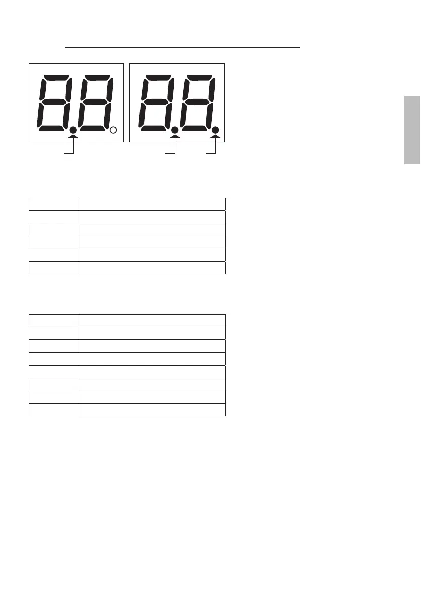
10.2 Command and safety device status display mode
COMMAND STATUS SAFETY DEVICE STATUS
AP PED
ORO
FT1
COS1
COS2
FT2
FA
FC
PP
CH
POWER STOPSB
COMMAND STATUS:
The command status indicators on the display are normally OFF.
They ILLUMINATE when a command is received (e.g.: when a step mode command is received, the segment PP
illuminates).
SEGMENT COMMAND
$3
open
33
step by step mode
&+
close
3('
partial opening
252
clock
SAFETY DEVICE STATUS:
The safety device status indicators on the display are normally ON.
If an indicator is OFF, the relative device is in alarm state or is not connected.
The an indicator is FLASHINGYMJWJQFYN[JIJ[NHJMFXGJJSINXFGQJI\NYMFXUJHNܪHUFWFRJYJW
SEGMENT SAFETY
)7
photocell
)7
photocell
&26
sensing edge
&26
sensing edge
)$
gate open limit switch
)&
gate closed limit switch
6%
release handle open