Do you have a question about the Roger SL2000F and is the answer not in the manual?
Details about the REL1 and OUT1 output configuration and signaling.
Explains the momentary control signal for devices like door strikes.
Describes the bistable control for systems like alarm zones.
Details the fixed function of OUT2 for Door Bell and Door Alarm signals.
The MASTER code is used to switch the SL2000 between Armed and Disarmed modes.
The INSTALLER code is required to enter the Installer Programming mode.
These codes are used solely to trigger the Door Lock (momentary) output.
Explains the meaning and programming of configuration parameters C1 through C10.
Provides an example of entering configuration digits during Memory Reset.
Lists the default MASTER, INSTALLER, and USER codes after a Memory Reset.
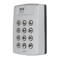
Provides guidance on mounting and installing the SL2000 code lock.
Details the terminal numbers, wire colors, and descriptions for connections.
Lists the available product models and their descriptions.