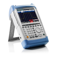
R&S FSH Measurement Equipment and Accessories
1145.5973.82 2.7 E-11
Adjusting the level accuracy
Test equipment - Signal generator (refer to section "Measurement Equipment and
Accessories ", item 1)
- Power meter (refer to section "Measurement Equipment and
Accessories ", item 3)
- Power sensor (refer to section "Measurement Equipment and
Accessories ", item 4)
- 6-dB power splitter (refer to section "Measurement Equipment and
Accessories ", item 2)
Determining the level accuracy at 100 MHz
Test setup Connect the power sensor (item 4) to the power meter and execute
function ´ZERO´ when there is no signal applied to the power
sensor.
Connect the RF output of the signal generator to the input of the
divider.
Connect output 1 of the divider to the power sensor / power meter.
Connect output 2 of the divider to the RF input of the R&S FSH.
Signal generator settings - Frequency 100 MHz
- Level 6 dBm
Determine the output power of the signal generator with the power
meter. Adjust the output power of the generator until the power
meter shows the expected level “Ampt”. This level is displayed on
the PC display during adjustment.
R&S FSH settings
- Performed automatically via the adjustment program.
Adjustment The program will guide you through the required adjustments for
different levels.
Save calibration data
If the measured values are within the programmed limits, the new
constants will be automatically stored in the R&S FSH and will be
used for future measurements.

 Loading...


