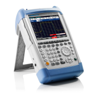
R&S FSH Module Replacement
1145.5973.82 3.13 E-11
Replacing the front unit for R&S FSH
Open the instrument.
Remove the battery .
Remove the Main Unit:
Disconnect the connectors (X3), (X4), and (X5).
Remove the main unit by unscrewing the two (S5) screws.
Remove the LCD colour module:
Losen the four (S6) screws.
Remove the LCD colour module.
Use the new front unit to assemble the instrument again.
Before mounting the unit, make sure that no dust is present between the front unit and
the LCD colour module.
Mount the LCD colour module with the four (S6) screws.
Mount the Main Unit with the two (S5) screws.
Connect the connectors (X3), (X4), and (X5).
Mount the battery.
Close the instrument.
Perform the quick verification test.
Refer to Chapter 2 “Adjustment”.
X3
X4
X5
X5
X4
S5
S5
S6
S6
S6
S6
MainUnit
ColorLCD
Module
X3
X6
Fig. 3-8 Replace Front Unit

 Loading...


