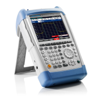
R&S FSH Module Replacement
1145.5973.82 3.17 E-11
Replacing the N connector
Open the instrument.
Remove the battery.
Remove the RF/IF module by unscrewing (S7).
Disconnect the flat cable (X8).
Disconnect the connectors (X7) and (X9).
Remove the binder and BNC connector block:
Loosen the four (S8) screws.
Remove the connector block.
Loosen the two screws (S9) from front RF housing for each N connector.
Loosen the 9 screws (S10) from the RF housing.
Remove the front RF housing.
Clean the center contact of solder left from the N connector to be replaced.
Loosen the other two screws (S9) from the appropriate N connector.
Mount the new connector by first screwing it into the rear RF housing.
Solder the center connection.
Mount the front RF housing (S10).
Fasten the two screws (S9) to the front RF housing for each the N connector.
Mount the binder and BNC connector block with the (S8) screws.
Mount the flat cable (X8), including the ferrite.
Connect the connectors (X7) and (X9).
Mount the RF/IF module (S7).
Mount the Battery and close the instrument.
Perform the manual adjustment.
Refer to Chapter 2 “Adjustment”.
X10
S10
S10
S10
S10
S10
S9
S9
S9
S9
S8
S8
S8
S9
S9
Binder and BNC
Connector Block
Rear RF Housing
Front RF Housing
Fig. 3-12 Replacing the N-Connector

 Loading...


