Instrument tour
R&S
®
RTA4000
22Getting Started 1335.7881.02 ─ 05
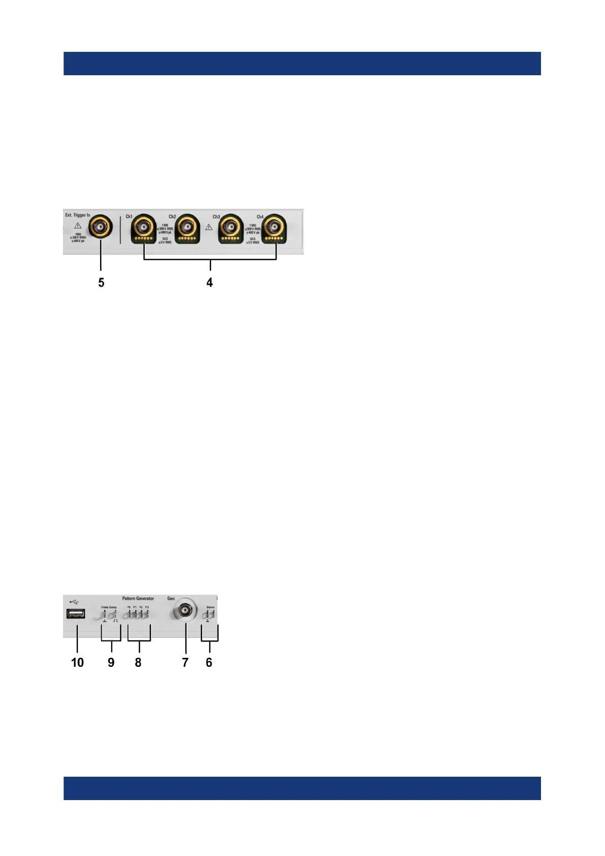
9 = Connectors for probe compensation
10 = USB connector
11 = [Standby] key
4.1.1 Input connectors
BNC inputs (4 and 5)
The R&S RTA4000 has two or four channel inputs (4) to connect the input sig-
nals. The external trigger input (5) is used to control the measurement by an
external signal. The trigger level can be set from -5 V to 5 V.
For channel connectors, the input impedance is selectable, the values are 50 Ω
and 1 MΩ.
The maximum input voltage is 400 V (peak), 300 V (RMS) at 1 MΩ input impe-
dance and 30 V (peak), 5 V (RMS) at 50 Ω input impedance.
For the external trigger input, the maximum input voltage is 400 V (peak) and
300 V (RMS) at 1 MΩ input impedance.
Transient overvoltages must not exceed 400 V (peak).
4.1.2 Other connectors on the front panel
[Demo] (6)
The pins are intended for demonstration purposes.
Front view
 Loading...


