4.1.5
leasurigg
leads
(See
P
g.
4-
and
c1rcu
t
diagrams
395.0512
s,
395.2680
s,
395.1019
S
and
395.1619
S)
'The
12-way
connector
of
each
measuring
head
contains
a
data
memo-
ry,
in
which
all
characteristics
and
correction
values
required
for
the
measurement
are
stored.
The
data
are
read
out
either
when
the
instrument
is
switched
on
or
when
a
probe
is
exchanged.
For
this
purpose
the
data
memory
is
first
connected
to
the
5-V
supply
of
the
analog
board
via
relay
K101
and
its
content
is
then
read
out
in
serial
form.
The
EPROM
D12
is
addressed
via
the
two
casca—
ded
counters
D11
and
D10
by
increasing
the
address
by
one
after
every
8
clock
pulses.
The
parallel-serial
conversion
of
the
ad-
dressed
8-bit
word
is
effected
in
the
multiplexer
D13
which
upon
each
clock
pulse
(x1o.7)
addresses
the
next
higher
bit.
The
two
counters
D10/D11
are
reset
by
logic
H
via
x1o.9
at
the
beginning
of
the
read-out
process.
The
"chip
enable"
for
the
EPROM
D12
(lo-
gic
L)
is
also
effected
via
x10.9.
The
data
memories
are
driven
by
the
addressable
latch
D101
on
the
analog
board.
The
clock
pul-
ses
are
jointly
produced
for
both
probes
(D101.10),
reset/chip
enable
separately,
i.e.
for
channel
A
at
terminal
D101.9,
for
channel
B
at
terminal
D101.11.
The
outputs
of
the
data
memories
aggogaken
separately
for
the
two
channels
to
the
multiplexer
(26)
With
the
aid
of
the
probe
detector
(27)
it
is
possible
to
recog-
nize
whether
a
probe
has
been
inserted
in
the
basic
unit
or
re—
moved
from
it.
The
probe
detector
basically
consists
of
an
R/S
flipflop
for
each
of
the
channels
A
and
B,
which
with
non-opera-
tive
channel
is
set
by
the
corresponding
pull-up
resistor
(R523,
R524).
With
a
probe
inserted.
the
set
input
is
kept
at
logic
L
level
via
the
resistor
R13
(data
memory).
4.1.5.1
RP
Probe
URV5-27
The
RF
probe
is
made
up
of
a
full-wave
rectifier
which
is
capaci-
tively
coupled
to
the
test
input
and
supplies
two
rectified
vol-
tages
of
the
same
amount
but
with
opposite
polarity.
The
recti—
fied
voltages
are
further
boosted
in
the
basic
unit
by
the
probe
amplifiers
A
or
B.
In
order
to
compensate
for
the
relatively
strong
temperature-dependence
of
the
rectifier
diodes,
the
tempe-
rature
is
measured
in
the
vicinity
of
the
rectifier
diodes
by
means
of
the
sensor
V3
and
is
then
considered
in
the
microproces-
sor
calculations.
V3
acts
like
a
Zener
diode
with
temperature-de-
pendent
break-down
voltage
and
is
cyclically
switched
on
only
for
a
few
milliseconds
(N503.2)
in
order
to
minimize
errors
caused
by
selfheating.
394.801o.oz
4.7
3-3
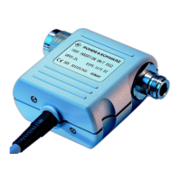
4.1.5
.easuring Heads
(See
Fig.
4-1
and circuit diagrams 395.0512 S, 395.26B0 S,
395.1019
S and
395.1619
S)
The 12-way
Connector
of
each
measuring
head
container
a
data
memo-
ry,
in which all characteristics and
correction
Values
required
for the measurement are
stored.
The
data
are
read
out
either
when
the Instrument is switched on er
when
a
probe
is
exchanged.
For
this
purpose
the
data
memory
is
First
connected
to the 5-v
Supply
of the
analog
board
via
relay
K101
and its
Content
is
then
read
out in serial form. The BPROM
D12
is addressed via the
toto
casca-
ded
counters
D1
1
and
D10
by increasing the address by
one
after
every 8 clock
pulses.
The parallel-serial
conversion
of the ad-
dressed
8-bit Word is effected in the multiplexer
D13
which
upon
each
clock
pulse
(X10.7)
addresses
the
next
high
er
bit.
The
toto
counters
D10/D11
are
leset
by logic H via
x10.9
at the beginning
of the
read-out
process.
The
'Chip
e fable'
for
the EPROM
D12
(1o-
gic L) is also
effected
via.-X10.9. The
data
memories
are
driver
by the
addressable
latch
D101
on the
analog
board.
The
clock
pul-
ses
are
jointly
produced
for
both
probes
(D101.10),
leset/chip
e fable
separately,
i.e.
for Channel A at terminal
D101.9,
for
Channel
B at terminal
D101.11.
The
Outputs
of the
data
memories
are
taken
separately
for the
toto
Channels to the
multiplexer
(26)
(DSOB).
With
the
ad
of the
probe
detector
(27)
it
is
possible
to
recog-
nize
whether
a
probe
has
been
inserted in the
basic
Unit er
re-
moved
fror it. The
probe
detector
basically
consists
of an R/S
flipflop for
each
of
the
Channels
A and B,
which
Voith
non-opera-
tive
Channel
is Set by the
corresponding
pull-up
resistor
(R523,
R524).
Voith
a
probe
inser
ted, the Set
Input
is
kept
at logic L
level via the
resistor
R13
(data
memory).
4.1.5.1
RF
probe
ÜRV5-Z7
The RF
probe
is
made
up of a full-wave rectifier
which
is
capaci-
tively
coupled
to the
test
Input
and
supplies
toto
rectified
vol-
tages
of
the
same
account
but
Voith
opposite
polarität. The
recti-
fied
voltages
are
fur
ther
boosted
in the
basic
Unit
by the
probe
amplifiers
A er 5, In
Order
to
compensate
:er
the
relatively
strong
temperature-dependence
of the
rectifier
diodes,
the
tempe-
rature
is
measured
in the
vicinity
of the
rectifier
diodes
by
ne ans of the
Sensor
$3 and is
then
considered
in the
microproces-
sor
calculations.
vag
acts
like
a Zener
diode
Voith
temperature-de-
pendent
break-down
voltage
and is
cyclica1ly
switched
on
only
for
a few
milliseconds
(N503.2) in oder to
minimize
errors
caused
by
selfheating.
394.3010.02
4.7
E-3
 Loading...


