- 1 -
PARTS
Genuine ROLAIR® replacement parts are sold nationwide through a network of authorized dealers and service centers.
Please contact the dealership where your air compressor was purchased or our factory Customer Service Department if
you need help troubleshooting, obtaining parts, or locating an authorized ROLAIR
® service representative.
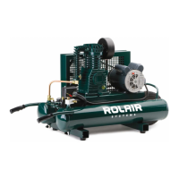
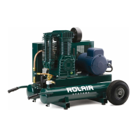
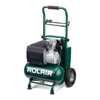
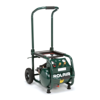
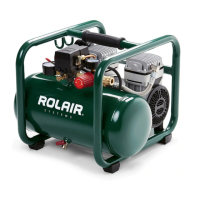
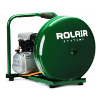
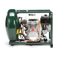
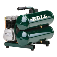
PORTABLE AIR COMPRESSOR
OWNER’S MANUAL
WARNING
COMPRESSOR DISCHARGE AIR MAY CONTAIN HYDROCARBONS AND OTHER
CONTAMINANTS! DO NOT USE DISCHARGE AIR FOR BREATHING!
RECORD OF PERTINENT INFORMATION
Make a permanent record of the model and serial number of your new air compressor here. You’ll save time and
expense by including this reference information when requesting service or replacement parts.
Place & Date of Purchase Volts
Model HZ
Serial # HP
With the tank gauge at 0 PSI and air line(s) disconnected, close drain valve(s) and record the amount of time it takes
to build tank pressure on the space provided. Periodically test your air compressor against this pump-up time to
determine if it is operating correctly. If time test is considerably off, contact your local ROLAIR
® representative to
arrange service.
From 0 to ______*PSI From 0 to ______*PSI
Date Min Sec Date Min Sec
To order replacement parts:
1. Give compressor model number
2. Give compressor serial number
3. Name of part
4. Part number
5. Quantity required
606 South Lake Street > P.O. Box 346 > Hustisford, WI 53034-0346 > 920.349.3281 > fax 920.349.3691 > www.rolair.com