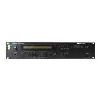
Do you have a question about the Roland D-550 and is the answer not in the manual?
| Brand | Roland |
|---|---|
| Model | D-550 |
| Category | Synthesizer |
| Language | English |
Detailed technical specifications for the D-550 unit.
Step-by-step instructions for taking the unit apart.
List of casing, panel, and structural parts.
List of buttons, knobs, connectors, and associated frames.
List of PCB assemblies, ICs, transistors, fuses, and other electronic parts.
List of diodes and various connectors for the D-550.
List of miscellaneous parts, battery, and memory card.
Data and pinouts for CPU, ROM, and RAM integrated circuits.
Data and pinouts for D/A converters, regulators, and other ICs.
Data and pinouts for logic gate and multiplexer ICs.
Pinout and function description for the Reverb custom IC.
Pinout and function description for the Chorus custom IC.
Pinout and function description for the Synthesizer custom IC.
Pinout and function description for Gate Array ICs.
Block diagram showing connections to peripheral boards.
Block diagram showing connections within the main board.
Block diagram showing connections to the volume board.
Troubleshooting steps for the digital to analog conversion section.
Checks for specific ICs and the LCD unit during troubleshooting.
Procedures for identifying ROM version and adjusting the DAC.
Procedure to restore Tone RAM data after replacement.
Steps to perform a test on the LCD unit.
Steps for testing the internal memory of the unit.
Steps for testing the front panel controls and indicators.
Notes and explanations for the memory and panel tests.
Diagram showing component placement on the main board.
Details on the piggybacked ROM PCB and PCM ROM replacement.
Schematic diagrams for panel, memory card, and other peripheral boards.
Schematic diagrams for the main processing and power supply boards.
Detailed schematic diagrams for Jack, Panel, Memory Card, and Volume boards.
Information on transmitted and recognized MIDI data.
Explanation of different MIDI modes and their settings.
Details on MIDI data transmission and reception flow.
Mapping of MIDI parameters, control changes, and reverb blocks.
Details on transmitting and receiving exclusive MIDI messages.
Procedures for one-way data transfer via exclusive messages.
Handshaking protocols for data transfer.