23
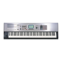
Fantom-S88
4. Expansion Board test
This tests the Expansion Board socket and peripheral circuits.
When you enter the Expansion Board test, the LCD display will show as
follows, and the Expansion Board test will begin automatically.
fig.4-1_70
If the test result is OK, you will automatically proceed to the next test item.
5. MIDI test
This tests MIDI connectivity.
When you enter the MIDI test without any MIDI cable connected between
MIDI IN and MIDI OUT, the LCD display will show as follows.
fig.5-1
Use a MIDI cable to connect the MIDI IN and MIDI OUT .
If the test result is OK, you will automatically proceed to the next test item.
6. Card
This tests the SmartMedia connector and peripheral circuits.
When you enter the Card test, the LCD display will show as follows.
fig.6-1_70
Insert the SmartMedia you provided (formatted; with protect label affixed)
into the SmartMedia slot.
When the test result is OK, the display will indicate “Protect=OK Please,
Remove The Card”.
When you remove the inserted SmartMedia, the display will indicate “Insert
The Card (Protect=OFF)”.
Next insert the SmartMedia (formatted; no protect label) into the SmartMedia
card slot.
When the test result is OK, the display will indicate “Read/Write=OK
Please,Remove The Card”.
When you remove the inserted SmartMedia, you will automatically proceed to
the next test item.
7. Sound test
This tests the audio input/output circuitry.
First you will test the [OUTPUT A L (MONO)] jack and [INPUT L/R] jack
circuitry.
Connect the stereo side of the PCS-31 to the [OUTPUT A L (MONO)] jack,
connect the PCS-31’s monaural L channel to the [INPUT L] jack, and the PCS-
31’s monaural R channel to the [INPUT R] jack. Insert a dummy plug into the
[OUTPUT A R] jack, and turn the [VOLUME OUTPUT] knob and [VOLUME
INPUT] knob all the way toward the right (MAX).
Verify that the LCD display shows a sawtooth wave and another sawtooth
wave (of inverted phase relative to the upper one) below, as follows.
fig.7-1_70
Next you will test the circuitry of the [OUTPUT A R] jack.
Connect the stereo side of the PCS-31 to the [OUTPUT A R] jack, connect the
PCS-31’s monaural L channel to the [INPUT L] jack, and connect the PCS-31’s
monaural R channel to the [INPUT R] jack. Turn the [VOLUME OUTPUT]
knob and the [VOLUME INPUT] knob all the way toward the right (MAX).
Verify that the LCD display shows a sine wave above and another sine wave
(of inverted phase relative to the upper one) below, as follows.
fig.7-2_70
When you press the [8] button you will proceed to the test of the [OUTPUT B
L/R] jack circuit.
Use an audio cable to connect the [OUTPUT B L] jack to the [INPUT L] jack,
and the [OUTPUT B R] jack to the [INPUT R] jack. Turn the [VOLUME
INPUT] knob all the way toward the right (MAX).

 Loading...