右左右左
右 左右 左
18
SP808-OP1
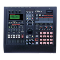
◎SP808-OP1 Multi I/O Expansion Board
*SCSI Connector (25-pin D-SUB type)
*Coaxial Digital In Connector
*Coaxial Digital Out Connector
*Optical Digital In Connector
*Optical Digital Out Connector
*Track Direct Out x 3, L, R (RCA phono type)
SP808-OP1
◎SP808-OP1マルチI/O拡張ボード
*SCSIコネクター(25ピンD-subタイプ)
*コアキシャル・タイプ・デジタル・イン
*コアキシャル・タイプ・デジタル・アウト
*オプチカル・タイプ・デジタル・イン
*オプチカル・タイプ・デジタル・アウト
*トラック・ダイレクト・アウトL、R×3(RCAピ
ン・タイプ)
SPECIFICATIONS/主な仕様
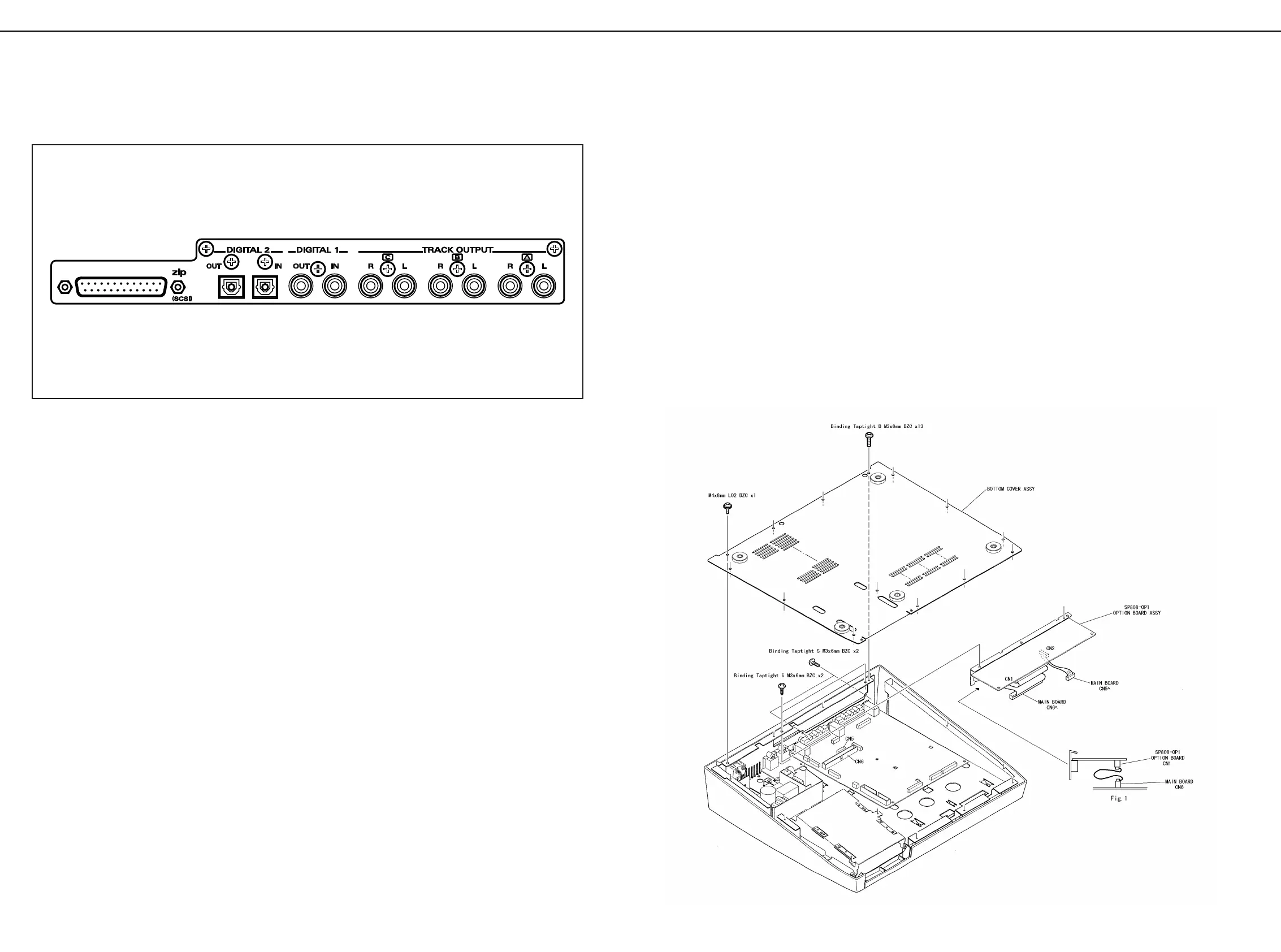
INSTALLING THE SP808-OP1/本体への取り付けについて (SP808-OP1)
1. Turn off the SP-808. Remove all connecting cables
from the SP-808.
2. Place the SP-808 upside down. Remove the bottom
cover.
3. Remove the EXP cover from the SP-808.
4. Plug in SP808-OP1 connector, with a length of the flat
cable bent, into the SP-808 main board connector.
See Fig. 1.
5. Screw-lock the SP808-OP1.
6. Attach and secure the SP-808 bottom cover.
7. Enter the test mode: holding down STATUS (track D)
and EFFECTS (track D) buttons of
RECORDER/MIXER, turn on the SP-808.
Verify that upper-right area of the screen displays
"OP-1".
8. Turn off the SP-808.
1.SP−808の電源を切り、SP−808に接続
しているケーブルを全て外します。
2.SP−808本体を裏返し、底面のカバーを外し
ます。
3.SP−808の EXPCOVERを外します。
4.SP−808の MAINBOARD上のコネクターに
SP808−OP1のコネクターを差し込みます。
注意:この時フラットケーブルを2つに折り込みます。
(Fig.1参照。)
5.ねじを締め、SP808−OP1を固定します。
6.SP−808の底板のカバーを元通りに取り付け
ます。
7.テストモードに入り、LCD右上に "OP-1"と表示
されていれば OKです。
参考:『テストモードの入りかた: RECORDER/MIX
部の[STATUS(Dトラック)]ボタンと[EFFECT
(D トラック) ]ボタンの2つのボタンを同時に押
しながら、SP−808の電源スイッチを入れ
ます。』
8.SP−808の電源を切ります。
SP808-op1
multi I/O expansion board for sp-808
SP-808/808Pro
Aug, 1998
 Loading...