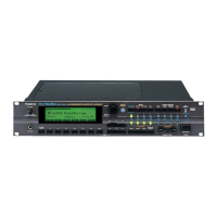
RS-5 Jan. 2001
18
Fig.4
Fig.3
Positioning reference Pin of chassisPositioning Pin of chassis
PWB Cutout Part
Projecting Part of chassisChassis Hook
******
:Secure with screw : No screw is required unless the chassis hook becomes useless.
Adjacent to PCBS
Fig.5
32 1
2) Align notch of the LOW PCB with projection from the chassis
and then insert the PCB into the chassis hook until the chassis's
positioning reference pin (located closest to the connector,
Fig.4) fits into the positioning reference hole of the PCB(Fig.3).
Then, engage all pins with holes. Repeat above steps for the HI
PCB.
3) Secure the LOW and HI PCBs with screws, while holding
the PCB at the center, and starting at the center screw
(1) and then (2) and (3). See Fig.5.
Screw at the locations illustrated.
Note: When using a power screwdriver, set the tightening
torque to 8kgf•cm to firmly secure the PCB without
damaging it. Overtightening will break foil
conductors.
<Removing the keyboard>
Holding the tip of the key, insert a pair of long nose pliers
into the U groove (shaded in Fig.6) and then push the key
in the direction of arrow.
<Installing the keyboard>
Fit the spring on the chassis, place the key as illustrated in
Fig.7 and then push the dotted circle line section in the
direction of arrow.

 Loading...