Do you have a question about the Roland udk20 and is the answer not in the manual?
Explains the meaning of warning and information icons used in the manual.
Provides crucial safety guidelines for operating the equipment and potential hazards.
Defines the specific applications and purpose for which the UDK20 is designed.
Details the specifications and features of the UDK20 control unit.
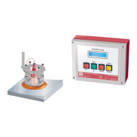
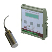
Lists and explains the different available versions of the UDK20 control unit.
Details specifications for sensors, including the PW42AGS model.
Provides data on measurement response times for FE materials under different conditions.
Details sensor performance data for non-ferrous materials, including conductivity and thickness limits.
Information on available sensor cables, including types and specifications.
Describes the specific sensor cable SCPWS used with the PW42AGS sensor.
Explains how to make sensor cable extensions.
Details the cable used for connecting the control unit to the Sensor Switch Box.
Explains the combined electromagnetic and eddy current principles used for measurement.
Provides guidelines for ensuring process security and stable measurement results.
Details the UDK20 control unit and its major features.
Covers system and program parameters for configuring the UDK20.
Illustrates typical use cases and examples for the UDK20 system.
Outlines general guidelines for installing the device to ensure accuracy and reliability.
Details dimensions for the UDK20 in an industrial enclosure.
Details dimensions for the UDK20-2PW with up to two sensors.
Details dimensions for front panel mounting enclosures.
Provides rules for reliable sensor mounting.
Lists items to observe and check for mounting contacting sensors.
Details the SH42GS spring-loaded sensor bracket and its dimensions.
Describes the SHS42GS spring-loaded bracket with a flat suction cup.
Details the SHS42GS bracket with flat suction cup for robotic destackers.
Describes the SHX42 spring mounted sensor holder and its features.
Details the SHX-AZ2-25 clamping bracket for fixing sensor holders.
Describes the SHS42G-FB bracket with bellow suction cup for robotic destackers.
Details the SHK clamping bracket for mounting spring loaded sensor brackets.
Illustrates common incorrect sensor mounting examples and their consequences.
Advises on avoiding electromagnetic interference affecting sensor accuracy.
Provides instructions for mounting the Sensor-Switch-Box SSBUDK10.
Outlines requirements for using Roland sensors within an ATC concept.
Advises on keeping sensor cables short to minimize electromagnetic noise influence.
Shows connector configuration for UDK20-x-x-S in industrial enclosure.
Shows connector configuration for UDK20-x-x-S-FP and UDK20-2PW-x-x-S.
Details the wiring and pin assignments for connecting the first sensor.
Details wiring and pin assignments for connecting the second sensor on 2PW units.
Explains the connection for the sensor switch box on specific unit versions.
Describes the RS232 connection setup for C version units.
Details how supply voltage and PLC I/O are connected via the central plug.
Shows PLC data inputs and relay outputs for Version B.
Shows PLC data inputs and opto coupler outputs for Versions B or C.
Provides a connection diagram for the UDK20 with a single sensor.
Shows the connection diagram for UDK20 with SSBUDK10 and four sensors.
Provides a connection diagram for the UDK20-2PW with two sensors.
Details the internal wiring of the SSBUDK10 Sensor Switch Box.
Lists available PLC inputs for external control and their functions.
Describes the available PLC output signals (Opto coupler outputs).
Explains summary output priorities and the ENABLE signal function.
Introduces timing diagrams and notes for their interpretation.
Details the procedure and timing for the system test function.
Explains how to select measurement programs using PLC inputs via timing.
Describes the timing for single measurement operation triggered by PLC.
Describes the timing for continuous measurement operation triggered by PLC.
Explains how to perform external zero adjustment using PLC inputs via timing.
Explains how to perform external Teach-In using PLC inputs via timing.
Recommends an operating cycle for reliable functioning in destacking applications.
Describes the demo mode for demonstration purposes only.
Guides on powering up the system and explains front panel operations.
Outlines the main menu, sub-structures, and general configuration rules.
Provides rules for operating in configuration mode.
Explains how to navigate and change configuration settings, including password entry.
Details how to configure program parameters like program number and sensor selection.
Guides on setting material, nominal thickness, and upper/lower limit values.
Explains the procedure for performing zero adjustment for sensors.
Details the procedure for performing Teach-In for material and thickness calibration.
Introduces system parameters and covers language, sensor type, and number of sensors.
Covers display dimensions, measuring modes, and measurement speed settings.
Covers FE Teach-In limits, program deletion, and password function.
Covers external calibration, output logic, and Teach-In factor diagnostics.
Details additional diagnostic views for parameters like nominal thickness and factors.
Guides on accessing W-diagnosis for conductivity, thickness, and frequency/gain.
Explains sensor demagnetization and how to exit diagnostics.
Shows indications for unit type, software/hardware versions, and system version.
Explains the data backup procedure using RS232 for system configuration and parameters.
Provides a brief overview of system operation, display, LEDs, and key functions.
Step-by-step guide for creating and configuring a new measurement program.
Explains how fault messages are displayed, their cause, and how to clear them.
Describes fault messages related to the Sensor-Switch-Box and their resolution.
Lists memory-related faults, their causes, and remedies.
Lists faults related to zero adjustment and their potential causes and remedies.
Lists faults related to the Teach-In process and their remedies.
Lists faults related to RS232 transmission and their remedies.
Lists faults related to the measuring operation and their remedies.
Lists faults related to the keyboard operation and their remedies.
Lists faults related to supply voltage issues and their remedies.
Lists faults related to the Sensor Switch Box and their remedies.
Lists faults related to PLC parallel inputs and their remedies.
Lists miscellaneous faults not categorized elsewhere and their remedies.
Provides instructions and precautions for replacing sensors, including the zero adjust procedure.
Guides on exchanging the control unit, with and without RPP-software.
Details the procedure for replacing fuses in the control unit.
Explains the process of backing up data via the serial interface.
Provides a brief description of the RPP-XP software for data backup.
Lists recommended minimum spare parts to be inventoried.
Details the procedure and prerequisites for replacing a UDK10 with a UDK20.
Lists and describes the different versions of the UDK20 control unit.
Lists available system accessories, such as the Sensor Switch Box.
Lists available sensors and related accessories with their specifications.
Lists available sensor cables with specifications and descriptions.
Lists available cable plugs and sockets for connections.
Lists other accessories like software and PC connection cables.
Provides a form for documenting system configuration settings.
| Brand | Roland |
|---|---|
| Model | udk20 |
| Category | Security Sensors |
| Language | English |