Manual
Double Sheet Detector R1000 series UDK20
B0048991 / Rev. 1.3
Table of contents
ROLAND ELECTRONIC GmbH · Otto-Maurer-Str. 17 · DE 75210 Keltern · Phone +49 (0)7236-9392-0 · Fax +49 (0)7236-9392-33
3
Declaration of conformity according to EC directives .....................................................................................7
1 Safety advices ........................................................................................................................................9
1.1 Declaration of icons...........................................................................................................................9
1.2 Safety instructions and warnings for user .........................................................................................9
1.3 Intended use ...................................................................................................................................10
2 Technical data ......................................................................................................................................11
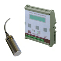
2.1 Technical data control unit UDK20 .................................................................................................11
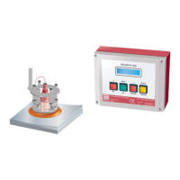
2.2 Versions of the control unit UDK20.................................................................................................13
2.3 Sensors ...........................................................................................................................................14
2.4 Sensor performance data (Measuring time) for ferrous (FE) material............................................15
2.5 Sensor data for non-ferrous (FE) material ......................................................................................18
2.6 Sensor cables .................................................................................................................................18
3 System description ..............................................................................................................................21
3.1 Measurement principle....................................................................................................................21
3.2 General hints for process security ..................................................................................................22
3.3 Control unit......................................................................................................................................23
3.4 Parameters of the control unit.........................................................................................................23
3.5 Application samples ........................................................................................................................28
4 Mounting ...............................................................................................................................................33
4.1 General mounting instructions ........................................................................................................33
4.2 Dimensions of the system ...............................................................................................................34
4.3 Mounting of sensors........................................................................................................................38
4.4 Automatic tool changer ...................................................................................................................51
5 Electrical installation ...........................................................................................................................52
5.1 General instructions ........................................................................................................................52
5.2 Configuration of connectors ............................................................................................................52
5.3 Connecting diagram - examples .....................................................................................................64
5.4 Internal wiring of the Sensor-Switch-Box SSBUDK10 ....................................................................67
6 Communication with the PLC .............................................................................................................68
6.1 PLC inputs.......................................................................................................................................68
6.2 PLC output signals..........................................................................................................................68
6.3 Timing diagrams..............................................................................................................................69
6.4 Internal control (Demo mode) .........................................................................................................79
7 Start-up..................................................................................................................................................80
7.1 Initially applying power to the system .............................................................................................80