Number of Channels
PROCESSING
48 inputs / 18 buses
CONNECTORS
Signal Processing
AD/DA Conversion
56-bit
24-bit / 44.1kHz or 24-bit / 48kHz
Network Latency
XLR Inputs (1 to 8 )
XLR-3-31 type (balanced with phantom power)
Talkback Mic Input
XLR-3-31 type (balanced with phantom power)
RCA Inputs (L/R)
RCA Pin Type
XLR Outputs (1 to 8 )
XLR-3-32 type (balanced)
Phone Output
Stereo 1/4 inch phone type
Digital Outputs
Optical type x 1 and Coaxial type x 1
REAC Ports
RJ-45 EtherCon type x 3
Remote Connectors
RS-232C (D-Sub 9 pin type) x 1*
MIDI (5 pin DIN type) x 2 (Out/Thru & In)
* Serial remote control is not available on version 1 firmware
USB Ports
A type x 1 and B type x 1
Other Connectors
LAMP (XLR-4-31 type) x 1, Grounding terminal, AC Input
2.8 ms (typical)
INPUT / OUTPUT CHARCTERISTICS
Non Clip Maximum Output level
Residual Noise Level (IHF-A, typical)
Equivalent Input Noise Level (E.I.N.)
Total Harmonic Distortion + Noise
Dynamic Range
Cross Talk@1kHz
Nominal Input Level (Variable)
XLR input jacks (1 to 8): -65 to -10 dBu (Pad: OFF) or -45 to +10 dBu (Pad: ON)
RCA input jacks (L/R): -18 to 0 dBu
Talkback input jack: -50 to -10 dBu
Input Impedance
XLR input jacks (1 to 8): 14 k ohms, RCA input jacks (L/R): 10 k ohms,
Talkback input jack: 41 K ohms
Non Clip Maximum Input level
XLR input jacks (1 to 8): +8 dBu (Pad: OFF) or +28 dBu (Pad: ON),
RCA input jacks (L/R): +18 dBu, Talkback input jack: +8 dBu
XLR output jacks (1 to 8): +4 dBu (Load impedance: 10 k ohms)
Nominal Output Level
Output Impedance
XLR output jacks (1 to 8): 600 ohms, Phones jack: 100 ohms
Recommended Load Impedance
XLR output jacks (1 to 8): 10 k ohms or greater, Phones jack: 8 ohms or greater
XLR output jacks (1 to 8): +22 dBu (1 kHz, 10 k ohms load)
Phones jack: 150 mW + 150 mW (1 kHz, 40 ohms load)
-88 dBu (All faders : Min)
-126 dBu
XLR output jacks (1 to 8): 0.05 % (typical), Phones jack: 0.05 % (typical)
XLR output jacks (1 to 8): 110 dB (typical)
XLR input jacks (1 to 8): -80dB (Pad: ON, Input gain: +10 dBu, typical)
XLR output jacks (1 to 8): -100 dB (typical)
OTHERS
Display
Power Supply
Power Consumption
Dimensions
Weight
800 x 480 dots Wide VGA backlit TFT full color
AC 115 V, AC 117 V, AC 220 V, AC 230 V, AC 240 V (50/60 Hz)
95 W
749.0 (W) x 626.0 (D) x 229.0 (H) mm, 29-1/2 (W) x 24-11/16 (D) x 9-1/16 (H) inches
19.8 kg, 43 lbs 11 oz
Frequency Response
XLR output jacks (1 to 8) : -2 dB / +0 dB (20k ohms load, +4 dBu)
Phones jack: -3 dB / +0 dB (40 ohms load, 15
0 mW)
(0dBu=0.775Vrms)
* When a REAC Splitter S-4000-SP or a switching hub is used in-line with REAC cables, the network latency will increase by the amount of processing delay introduced by the splitting device itself. The actual delay is dependent upon the specifications of the splitting device,
though the maximum delay amount for a single splitting device should be about 200 microseconds.
* In the interest of product improvement, the specifications and/or appearance of this unit are subject to change without prior notice.
* Total System Latency of audio signal from S-1608 inputs to
outputs via M-400's REAC ports (A or B).
* Sample Rate: 48.0 kHz
* Effects : No insert effects
Number of Channels
16 in 8 out
AD and DA Conversion
24-bit / 44.1kHz, 48kHz, 96kHz
Frequency Response
-2 dB / +0 dB (@ +4 dBu, 20 Hz to 20 kHz)
Total Harmonic Distortion + Noise 0.05 % or less (Pad: On, Input Gain: +4 dBu, 22 to 20 kHz)
Dynamic Range
110 dB
Nominal Input Level
-65 to -10 dBu (PAD: Off)
-45 to +10 dBu (PAD: On)
(1 dB step, Max. +28 dBu)
Input Impedance
14 k ohms
Nominal Output Level
+4 dBu, Max. +22 dBu
Output Impedance
600 ohms
Recommended Load Impedance
10 k ohms or greater
Residual Noise Level (IHF-A, typ.)
-80 dBu or less
Power Comsumption
POWER Indicator x 1, REAC Indicator x 1,
REMOTE Indicator x 1, MUTE ALL OUTPUTS Indicator x 1
Phantom Power
+48 V / 14 mA (each input, remote controlled)
S-1608: 45W
Power Supply
AC 115 V, AC 117 V, AC 220 V, AC 230 V, AC 240 V (50/60 Hz)
Dimensions
401.0 (W) x 135.0 (D) x 177.0 (H) mm or
15-13/16 (W) x 5-3/8 (D) x 7 (H) inches
Weight
4.5 kg or 9 lbs 15 oz
Indicators
Connectors
Analog Input x 16 (XLR type, balanced, phantom power)
Analog Output x 8 (XLR type, balanced)
Digital Output connector x 1 (Optical type)
REAC Connector x 1 (RJ-45 EtherCon type)
Remote Connector x 1 (RS-232C, DB-9 type)
PAD 20 dB On/Off
(0dBu=0.775Vrms)
Equivalent Input Noise Level
Network Latency
-128 dB
375 microseconds when using REAC cable only (*1)
(AD - REAC - DA Latency: approx 1.2 ms)
* In the interest of product improvement, the specifications and/or appearance of this unit are subject to change without prior notice.
*1 When a REAC Splitter S-4000-SP or a switching hub is used in-line with REAC cables, the network latency will increase by the amount of processing delay introduced by the splitting device itself. The actual delay is dependant upon the specifications
of the splitting device, though the maximum delay amount for a single splitting device should be about 200 microseconds.
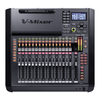
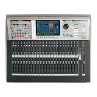
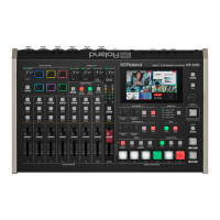
■ V-Mixer M-400 Specifications
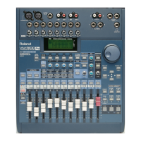
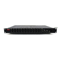
■ Digital Snake S-1608 Specifications
Power Cord x 1, REAC Connector Cover x 1, Ferrite Cores x 1
Rubber Foot x 4, Rack Mount Kit x 1, Owner's Manual
Accessories
 Loading...