IS2100-M Generation 2
Installation, Program & Operation Manual
www.rontan.com.br REV 1 Page
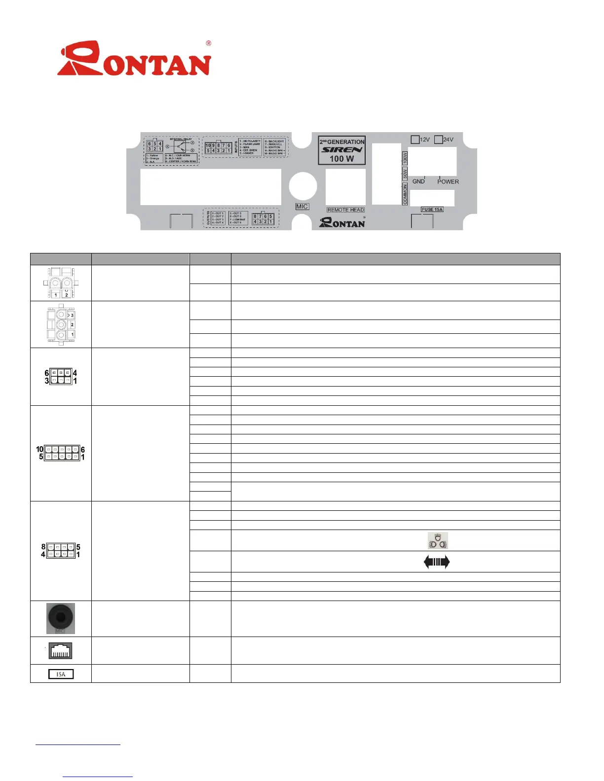
5 –Back Panel
The back panel has 8 connectors, identified below:
Figure 2: Back Panel
Negative Battery Terminal
Positive Battery Terminal
GND output for the 50 o 100W speakers
Output for the Siren 50W Speaker
Output for the Siren 100W Speaker
Serial Communication with Rontan’s lightbar
Serial Communication with Rontan’s lightbar
Hands Free Relay Contact N.C.
Hands Free Relay Contact N.O.
Hands Free Relay Contact COM / Input of the Steering Wheel Signal
Selection of the polarity of the Steering Wheel signal
Activates the lightbar in mode SL3
Activates the siren mode MAN 1
Activates the function I-Saver
Activates the light panel and the “Dimmer” (*)function
Deactivates the Siren tones
Input for the command Pos-Power
Activated by the buttons “1”, “2” and “3”
Activated by the buttons “2” and “3”
Activated by the button 3”
Activated by the button “ ”
Activated by the button “ ”
Activated by the button “Radio”
Activated by the function “Low-Bat” (See page 11)
Activated always that the IS2100-M G-II is on (function Radio-ON)
Connection for the remote control panel
Table 2: Connectors Description
Note: (*) When the Dimmer function is ON, the brightness intensity of the lightbar is reduced by 70%.
 Loading...