This manual is additionally available as a pdf file on rosebikes.com/manuals.
EN // OWNER’S MANUAL TOOL BOX // PROD. CODE: 2162687
General information / Safety
Please read this manual carefully before using the tools for the first time and make sure you understand everything. Keep this manual for future
reference. If you sell or give away your tool box, please also include the owner’s manual.
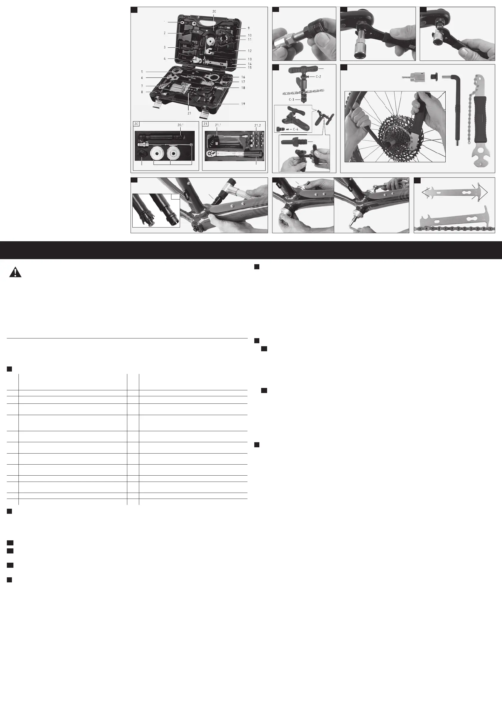
A
Contents
1
Chainring bolt tool with built-in wrench (9/10mm) and 2-pin
spanner for the removal/installation of integrated crank pullers
(16.5 mm spacing)
14 1/2“ adapter for tools with 1/2” fitting
2 Cleaning brush 15 Chain wear gauge for all 7 to 12 speed chains with 1/2“ pitch
3 Master link pliers 16 Bottom bracket tool for Shimano Hollowtech II cranks
4
Cable and housing cutter for inner cables and housings
(not for hydraulic brake hoses)
17
Shimano/SRAM HG/IG cassette lockring tool with 1/2” socket or
24 mm open-end wrench
5
Bottom bracket tool for Hollowtech II or similar, as well as for
SM-BB9000, SM-BB93, BB-R9100 and SM-BBR60, BB-MT800
18
Bottom bracket tool for Octalink, square and ISIS bottom
brackets with splines, for 24 mm open-end wrench or ½“
ratchet
6
Chain whip for all 7 to 12 speed cassettes, 17mm open-end
wrench and 15mm pedal wrench
19
Chain tool, suitable for 7-/8-/9-/10-/11-speed chains and
Campagnolo HD Link™/Ultra Link™ chains, incl. spare tip pin
7
L-type hex wrench set (T-10/T-15/T-20/T-25/T-27/T-30/T-40/T-
45/T-50)
20.1
Removal tool for Shimano Pressfit BB86/92 and BB30 bottom
bracket cups
8
Crank puller for square taper, Octalink, ISIS cranks with
integrated hex socket
20.2 Removal adapter for BB30
9 Tyre lever with metal core 20.3
Tool with threaded rod and press-in cups for Shimano/SRAM
Pressfit BB86/92 and BB30/PF30 bottom bracket cups
10 Chain keeper for chain removal/installation 21.1 L-type hex wrench set (2mm/2.5mm/3mm/4mm/5mm/6mm)
11 Spoke wrench (3.2/3.3/3.5/4.0mm) 21.2
3/4/5/6/8/10 mm hex, 5 mm hex extension (8 cm), T20/T25/
T30 star
12
15 mm pedal wrench
21.3 Torque wrench 2-24 Nm (1/4“)
13 8mm hex wrench
B
How to use the crank puller (A/8)
As many manufacturers offer specific crank systems, you should check the documents of the crank manufacturer for any specific information about
crank removal first. The following procedure only describes the removal of standard ISIS, Octalink or square taper cranks without manufacturer-
specific features.
The crank extractor may be used to remove ISIS, Octalink or square taper cranks.
B1
Thread the nut completely onto the driver of the crank puller.
B2
Thread the crank puller into the crank as far as possible and slightly tighten it with a 15 mm wrench (A/12).
ATTENTION: Crank threads may be damaged if the crank puller nut is not completely threaded into the crank!
B3
Turn the driver clockwise with a 15 mm wrench (A/12) or a 14 mm hex wrench until resistance is felt. Continue turning the handle until the
crank can be removed. Remove the crank puller from the crank.
C
How to use the chain tool (A/17):
How to remove a chain pin:
1. Place the chain into the chain tool and tighten the retaining bolt (C-3) to lock it in place.
2. Turn the handle (C-1) and push the chain pin all the way out.
How to insert a chain pin:
1. Take the open ends of the chain and join them with a chain pin.
2. Place the chain into the chain tool and tighten the retaining bolt (C-3) to lock it in place.
3. Adjust the alignment bolt (C-2) to the desired depth.
4. Turn the handle (C-1) and push the pin into the chain.
Before fitting a Campagnolo chain, make sure to thread the peening anvil (C-4) into the retaining bolt.
How to replace a chain pin
If the chain pin is worn you can replace it with the included replacement pin.
1. Remove the replacement chain pin (C-5) from the base body of the chain tool.
2. Completely remove the extractor bolt (C-1) from the chain tool.
3. Put the bolt together with the worn pin into the multi-tooth mount on the base body of the chain tool and remove the chain pin from the
bolt.
4. Screw the replacement pin onto the bolt and tighten it with the multi-tooth mount.
DANGER
Improper use of tools may lead to serious injuries or damages!
Improper use or handling of the tools and using the tools for incompatible components may lead to damages and sudden failure of bike parts!
• Bicycle maintenance works require experience in handling bike components and must only be carried out by people with sufficient expertise.
• Please note the component manufacturers’ instructions.
• Once a chain has been riveted, you should not break the same link repeatedly.
• A chain must not be opened and re-joined more than two times. The distance between the subsequently installed chain pins should be as large
as possible.
• Do not use a chain pin to join chains with a master link. Make sure to fit an appropriate connector link to these chains instead.
• A chain that is too long or too short may have a significant influence on the functioning of the drivetrain.
• In case of any questions or if in doubt, seek the assistance of a qualified bicycle mechanic.
D
How to use the cassette lockring tool (A/13)
Lockring removal
1. Fit the lockring tool (A/13) to the 1/2” adapter (A/14).
2. Fit the cassette lockring tool with the adapter onto the lockring of the cassette.
3. Fit an 8 mm hex wrench (A/15) into the adapter.
4. Use the chain whip (A/6) to hold the cassette cogs in place.
5. Turn the cassette lockring tool counter-clockwise with the 8 mm hex wrench until it is removed.
Lockring installation
1. Clean and grease freehub body and cassette.
2. Fit the cassette onto the freehub body.
3. Fit the lockring tool (A/13) to the 1/2” adapter (A/14).
4. Fit an 8 mm hex wrench (A/15) into the adapter.
5. Tighten the cassette lockring. Please follow the torque specifications of the manufacturer!
E
How to use the Pressfit bottom bracket tool
E1
How to remove Press Fit bottom brackets
1. Remove the crank according to the manufacturer’s instructions.
2. Fit the appropriate adapter for BB86/92 or BB30 bottom brackets to the removal tool (A/20.1) and slide the adapter to the front of the tool
(see picture E1/A)
3. Pass the bearing remover through the bottom bracket and push against the bottom bracket cup you would like to remove.
à Once the tool is pressed against the bearing inside surface, the adapter will expand (see picture E1/B).
4. Carefully drive out the bearing unit with a hammer.
5. Repeat to drive out the second bearing.
E2
How to remove Press Fit bottom brackets
1. Carefully read the installation instructions for the bottom bracket and bike frame and prepare the bottom bracket and BB shell for
installation according to the manufacturer’s instructions.
2. Position one bottom bracket cup on each side of the BB shell.
3. Fit the correct side of the press-in cups (A/20.3) to the bearing cups.
4. Fit a washer and a sleeve (A/20.3) to the threaded rod and pass the rod through the press-in cups, the bottom bracket and the frame.
5. Fit a second washer and a second sleeve to the threaded bar and screw on the nut.
6. Make sure the bearing cups will go in straight.
7. Tighten the nut to press in the BB cups without getting them tilted and jammed.
8. Remove the tool and fit the crank according to the manufacturer’s instructions.
F
How to use the chain wear indicator (A/15)
The chain wear indicator allows you to keep track of chain wear. Replacing a chain in time may reduce premature wear of cassette and chainring
caused by chain stretch! The chain wear indicator comes with 2 different sides:
• The side with the “.75” marking is suitable for drivetrains with aluminium or titanium sprockets. If this side completely drops in between two
chain rollers, the chain wear factor has reached 0.075 mm per link and the chain should be replaced.
• The side with the “1.0” marking is suitable for drivetrains with steel sprockets. If this side completely drops in between two chain rollers, the
chain wear factor has reached 0.1 mm per link and the chain should be replaced.
How to measure chain wear
1. Place the dent of the chain wear gauge (F1) on a chain roller.
2. Place the measurement hook (F2) onto the chain.
If the measuring pin completely drops between the chain rollers so that the indicator lies flat on the chain, the chain should be replaced.
How to use the torque wrench (A/21.3)
1. Make sure you can still read the scale when holding the torque wrench in your hand.
2. Turn the lower part of the handle (twist grip) to set the desired torque in Newton meters (Nm).
The adjustment range is 2-24 Nm. The red bar indicates the set torque value. Once the torque is pre-set, you can use the torque wrench.
3. Fit the proper socket to the square drive and turn the handle until you hear a clicking noise.
Immediately stop tightening the bolt when the pre-set torque value has been reached (clicking sound). At low torque settings, it may be
harder to feel and hear the click.
4. Press the button on the top end of the torque wrench to remove the socket.
5. After use, adjust the value to the lowest torque setting to relieve tension on the internal mechanics (not below 2 Nm).
Important information
• Torque is measured in clockwise direction only!
• Not suitable for loosening stuck bolts.
• If the wrench has not been used for a long period of time, operate it several times at a low torque setting. This will allow internal lubricant
to recoat moving parts.
• Never set a torque value lower than 2 Nm or higher than 24 Nm.
• Immediately stop pulling the wrench when the torque setting has been reached.
• The wrench is shipped ready to use, calibrated and tested to an accuracy of +/- 4%.
• The torque wrench is a precision measuring instrument. Handle with care and store properly.
How to use the cable and housing cutter (A/4)
The cable and housing cutter is designed for cutting cables and housings and for fitting end caps.
Not suitable to cut hydraulic brake hoses!
If the cutting performance decreases or if there’s play, tighten the nut on the cutting head with a 12 mm hex wrench.
Maintenance and Care
Regular care and maintenance ensure high durability and reliability, as well as unlimited functionality. ROSE Bikes recommends carrying out the
following tasks:
• Handle the tools with care and make sure to protect them from damages and corrosion during storage. A proper functioning of the tools
largely depends on their condition.
• Regularly clean the tools and grease the metal parts with universal oil to prevent corrosion.
• Clean the torque wrench with a dry cloth. Never use any type of liquid or cleaner.
B1
A
C
D
B2
B3
20.1
20.1
AB
20.3
1.0
0.75
F2
F1
E1 E2
F
 Loading...