8-port Gigabit Desktop Switch RC-410LX User Manual
Chapter 3 Identifying External Components
This Chapter describes the front panel, rear panel and LED indicators of the Switch.
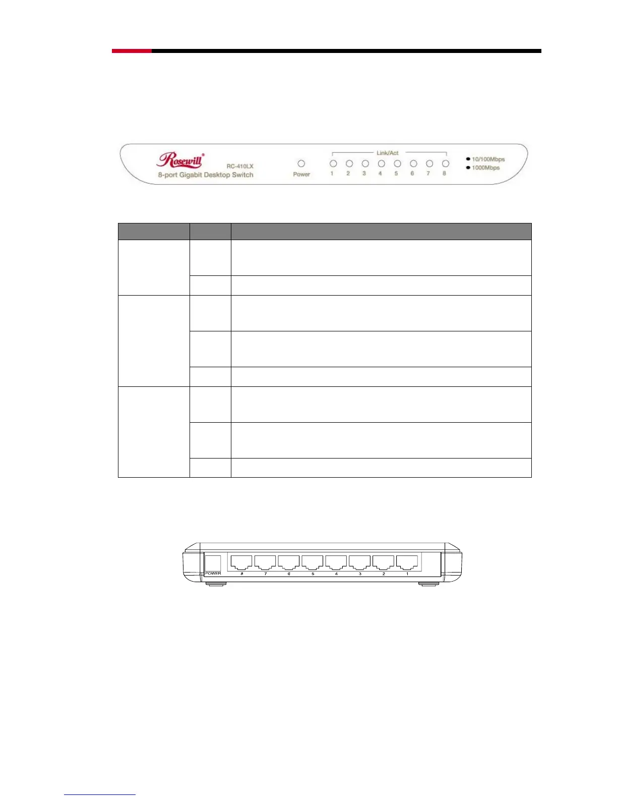
Front Panel
Figure 3-1 RC-410LX Switch Front Panel
The Switch’s LEDs are located on the front panel (View from left to right).
Name Status Indication
On
(green)
Power on
Power
Off Power off
On
(green)
There is a 1000Mbps device connected to the corresponding port.
Flashing
(green)
Data transmitting or receiving on corresponding port.
1000Mbps
Off No 1000Mbps device connected to the corresponding port.
On
(yellow)
There is a 10/100Mbps device connected to the corresponding port.
Flashing
(yellow)
Data transmitting or receiving on corresponding port.
10/100Mbps
Off No 10/100Mbps device connected to the corresponding port.
Note:
The LEDs’ description above explains the device’s working status after initialization.
Rear Panel
Figure 3-2 RC-410LX Switch Rear Panel
The following parts are located on the rear panel (View from left to right).
POWER: The POWER socket is where you will connect the power adapter. Please use the power
adapter provided with this RC-410LX Switch.
Port (1-8): The RC-410LX Switch is equipped with 8 x 10/100/1000M RJ45 ports where you will
connect your network devices. The working status can be indicated by the corresponding LEDs on
the front panel.
- 8 -
 Loading...