Thank You!
You have purchased a premium-quality ROSS
®
pneumatic valve.
It is a poppet valve with metal internals designed for inline mounting,
and has been built to the highest standards.
Pneumatic equipment should be installed only by
persons trained and experienced in such installation.
High- and Low-Temperature Valves:
Temperature specifications are given on page 2. Valves
whose model numbers end with a 001, 011, 051, or 061
are valves designed for high-temperature service. Valves
whose model numbers end with a 002, 003, 012, 013, 052,
053, 062, or 063 are valves designed for low-temperature
service.
Special Valves: If the second digit after the center letter
in your valve's model number is an 8 or 9, then your valve
has special features, (e.g. D2173B3952). You may consult
ROSS Technical Services to verify the special features or
to obtain high-pressure and vacuum service kits.
Air Lines: Before installing a valve in a new or an existing
system, the air lines must be blown clean of all contaminants.
It is recommended that an air filter be installed in the inlet
line close to the valve.
Valve Inlet (Port 1): Be sure that the supply line is
of adequate size and does not restrict the air supply
because of a crimp in the line, a sharp bend, or a clo
gged filter element.
Valve Outlets (Ports 2 and 4): For faster pressurizing
and exhausting of the mechanism being operated by
the valve, locate the valve as close as possible to the
mechanism. The lines must be of adequate size and be
free of crimps and sharp bends.
Valve Exhausts (Port 3): Do not restrict the air flow from
the exhaust port of the valve body or pilot body as this can
adversely affect the operation of the valve.
However, to reduce exhaust noise, an efficient silencer
may be used. ROSS silencers reduce impact noise by as
much as 25 dB, and produce little back pressure.
Electrical Supply: The voltage and hertz ratings of the
valve solenoids (if any) are shown on the pilot housing.
The electrical supply must correspond to these ratings.
Otherwise the solenoids are subject to early failure. The
power supply must be capable of handling the inrush
current without significant voltage drop.
See Valve Specifications on page 2 for information on
inrush current.
Operating Pressures and Temperatures: Allowable
ranges for pressure and temperatures are given in the
Valve Specifications on page 2. Exceeding the values
shown can shorten valve life.
Pilot Supply:
Pressure Control: Connect a 1/4-inch control line to the
threaded port in the air head at the top of the valve. See
Valve Specifications on page 2 for required pressures.
Solenoid Control: Pressure for the pilot valve is supplied
internally for most valves and requires no special connection.
However, if your valve is designated for external pilot supply,
a 1/8-inch pilot supply line must be connected to port X-1
in the pilot housing. See Valve specifications on page 2 for
pressure requirements.
Pipe Installation: To install pipe in valve ports, engage
pipe one turn, apply pipe thread sealant (tape not
recommended), and tighten pipe. This procedure will
prevent sealant from entering and contaminating the
valve.
21
Series
Poppet Valves
For High Temperature and Low Temperature Applications
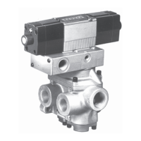
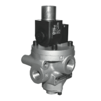
Single Solenoid
Pilot Controlled Valve
Direct Double Solenoid
Pilot Controlled Valve
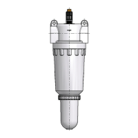
Pressure
Controlled
Valve
ROSS CONTROLS
®
Important Note: ROSS 21 Series valves are not designed as control valves for air clutch/brake mechanisms on
mechanical power presses, and must not be installed for such use. Only double valves conforming to OSHA standards
should be used in such applications.