This document provides operating instructions for Rossi EP series planetary gear reducers and gearmotors, part of the Habasit Group. It covers handling, installation, and maintenance, emphasizing safety and proper usage to ensure longevity and prevent damage.
Function Description
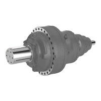
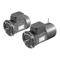
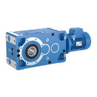
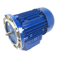
The Rossi EP series planetary gear reducers and gearmotors are designed to transmit power, reducing rotational speed and increasing torque. They are suitable for industrial applications, offering robust performance and reliability. The devices can be supplied as gear reducers (without a motor) or as gearmotors (integrated with an electric or hydraulic motor). A key feature is the availability of various output designs, including slewing outputs (R-S-H) and hollow shafts, catering to diverse application requirements. Some models include a backstop device to prevent counter-rotation, enhancing safety and control. The universal input flange allows for adaptation to different motorization types, providing flexibility in system integration.
Important Technical Specifications
General:
- Ambient Temperature Range: Standard operation from 0 °C to +40 °C, with peaks from -20 °C to +50 °C. Extended range from -40 °C to +60 °C is possible with specific evaluation of operating conditions, lubricant, seals, and cooling/heating systems.
- Storage Temperature: -10 °C to +50 °C.
- Vibration Speed: Veff ≤ 3.5 mm/s for PN < 15 kW and Veff ≤ 4.5 mm/s for PN > 15 kW.
- Screws and Tightening Torques: Class 10.9 screws are generally required, with class 12.9 for heavy stresses, alternate loads, and shocks. ISO 7089 washers (300 HV min.) must be used with class 12.9 screws. Tightening torques are specified in tables, valid for a friction coefficient of µ = 0.14.
- Painting: Internal painting uses single-compound ester epoxy or phenolic resin primer. External painting uses the same primer plus water-soluble polyurethane dual-compound enamel (final color Blue RAL 5010), resistant to atmospheric and aggressive agents (C3 category according to ISO 12944-2).
Lubrication:
- Lubricant Type: Synthetic PAO oil (ISO VG 320) is standard for sizes 001A-021A. Sizes 022A-710A are supplied without oil and must be filled with synthetic or mineral oil. EP (extreme pressure) additives are required.
- Oil Temperature: Minimum oil temperature for partial load starting is -20 °C (synthetic) or -10 °C (mineral). For full load starting, -10 °C (synthetic) or -5 °C (mineral). Maximum nominal stabilized oil temperature is +95 °C. Maximum peak/occasional oil temperature is +110 °C.
- Oil Change Intervals: Dependent on oil temperature:
- ≤ 65 °C: 12,500 h (synthetic), 5,600 h (mineral)
- 65-80 °C: 10,000 h (synthetic), 2,800 h (mineral)
- 80-95 °C: 6,300 h (synthetic), 1,400 h (mineral)
- Independent of running times: every 2-4 years (synthetic), every 1-2 years (mineral).
Cooling Unit Systems:
- Integrated Water Cooling Unit: Max water temperature 20 °C, minimum flow 3 dm³/min, pressure 0.2-0.4 MPa.
- Independent Cooling Units (UR O/A - Oil/Air, UR O/W - Oil/Water): Consist of oil/air or oil/water heat exchanger, motor pump, motor fan (for O/A), oil filter, manometers, thermometers, and pressure switches. Flow rate should not exceed 50% of the lubricant volume.
PB Series - Parking Brakes:
- Function: Spring-applied, hydraulic-released multi-disc brakes, used for holding loads or emergency stops. Not for service braking or dynamic conditions.
- Static Braking Torque (MBstat): Values vary by model (e.g., PB10-0075: 72 Nm, PB90-4250: 4305 Nm) with a tolerance of ±10%. May reduce by 5-10% after some braking cycles.
- Release Pressure (p): Varies by model (e.g., PB10-0075: 6.9 bar, PB90-4250: 56.9 bar).
- Max Release Pressure (Pmax): 300 bar.
- Max Back Pressure Allowed: 0.5 bar.
- Lubrication: Supplied without oil. Fill with mineral oil ISO VG 32. Separate lubrication prevents contamination of the gear reducer.
- Operating Conditions: -20 °C to +50 °C, max altitude 1000 m. For -20 °C to 0 °C, limit Pmax to 200 bar.
Usage Features
- Name Plate: Each unit has an anodized aluminum name plate with essential identification data, which must remain integral and readable.
- Lifting and Handling: Use designated attachment points and appropriate lifting equipment. Avoid lifting by input shaft threads.
- Installation: Requires a plane, leveled, and strong connection structure. Careful alignment with motor and driven machine is crucial, using flexible couplings where possible. Ensure free air passage for cooling. Apply locking adhesives on mating surfaces for external radial loads or high torque.
- Shaft Mounting: For shaft-mounted units, support both axially and radially. Torque arms should be used symmetrically to distribute reaction forces evenly. Hollow shaft mounting with shrink disc requires careful degreasing and specific tightening sequences.
- Pinion Gear Mounting: When mounting a pinion gear, verify backlash with the slewing bearing or rack to ensure correct meshing. Meshing clearance adjustment is achieved by rotating the gear reducer to position the point of maximum eccentricity.
- Motor Mounting: Check mating dimensions according to IEC 72-1 or NEMA C-FACE standards. Ensure proper keyway clearance and lubricate surfaces. Tighten motor fastening screws to specified torques.
- Commissioning: Before starting, perform a no-load run to check for correct operation, noise, vibrations, and sealings. Ensure proper oil filling and breather plug installation.
- Backstop Device: Allows rotation in one specific direction, preventing counter-rotation. Verify correct direction according to application requirements.
- Parking Brakes: Hydraulically released, spring-applied. To release, connect to a hydraulic circuit and bleed off air. Use mineral-based hydraulic oil.
Maintenance Features
- Regular Checks (at rest): Clean external surfaces and air passages, check oil level and deterioration, and verify fastening screw tightening.
- Regular Checks (during operation): Monitor noise level, vibrations, and sealings.
- Oil Change: Follow specified intervals. For oil draining and filling, use designated plugs. Wash the inside of the housing with the same oil type, filter it, and clean magnetic plugs. Refill with new oil of the correct type and viscosity.
- Seal Change: Replace seals when disassembling or during periodic checks. Position new rings to avoid previous sliding races.
- Re-greasing (Slewing Output Bearings): For R-S-H designs, output bearings have independent grease lubrication. Re-grease at the same intervals as oil changes, using the same grease type. It is recommended to re-grease before oil change to expel grease into the oil lubrication area.
- Troubleshooting: A table is provided for common issues (excessive temperature, anomalous noise, lubricant leakage) with possible causes and corrective actions. In case of persistent malfunctions or during the warranty period, consult Rossi S.p.A. before disassembling or opening the gear reducer.
- Overpressure: After running, gear reducers may have slight internal overpressure. Wait until the unit is cold before loosening plugs, or take necessary protection measures against warm oil contact.