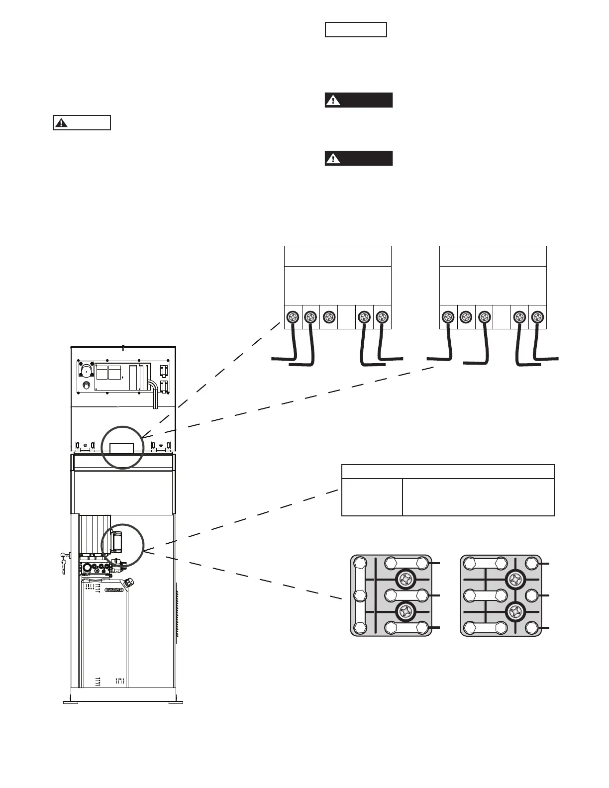
10. Control Cabinet Connections
Electrical Connection:
Have a certified electrician run appropriate power
supply to motor wire size for a three phase 10 amp. or
single phase 30 amp. circuit.
CAUTION
Never operate the motor on line voltage
less than 208V. Motor damage may occur.
All wiring must conform to all national and local
electrical codes.
IMPORTANT
Use seperate circuit for each power
unit. Protect each circuit with a time delay fuse or
circuit breaker. Use a 10 amp. (three phase) or 30 amp.
(single phase) fuse.
Make sure that the main power
supply is disconnected to avoid the possibility of
electrocution.
WARNING
All connections made inside the control
panel must be kept 457mm off of the floor.
T7
T1
T8
T2
T9
T3
T4
T5
T6
L1
L2
L3
11 12
Green
230V
Blue
13 14 15 16
T7
T4
T1
L1
T8
T5
T2
L2
T9
T6
T3
L3
208-230V
50/60Hz. 1Ø
380V
50 Hz. 3Ø
Transformer
11 12
Green
380V
Blue
13 14 15 16
POWER UNIT VOLTAGE RANGE
LINE VOLTAGE RUNNING MOTOR VOLTAGE RANGE +/-10%
230V 50/60Hz. 1
Ø 208-253V
380V 50Hz. 3
Ø 342-418V
11
 Loading...