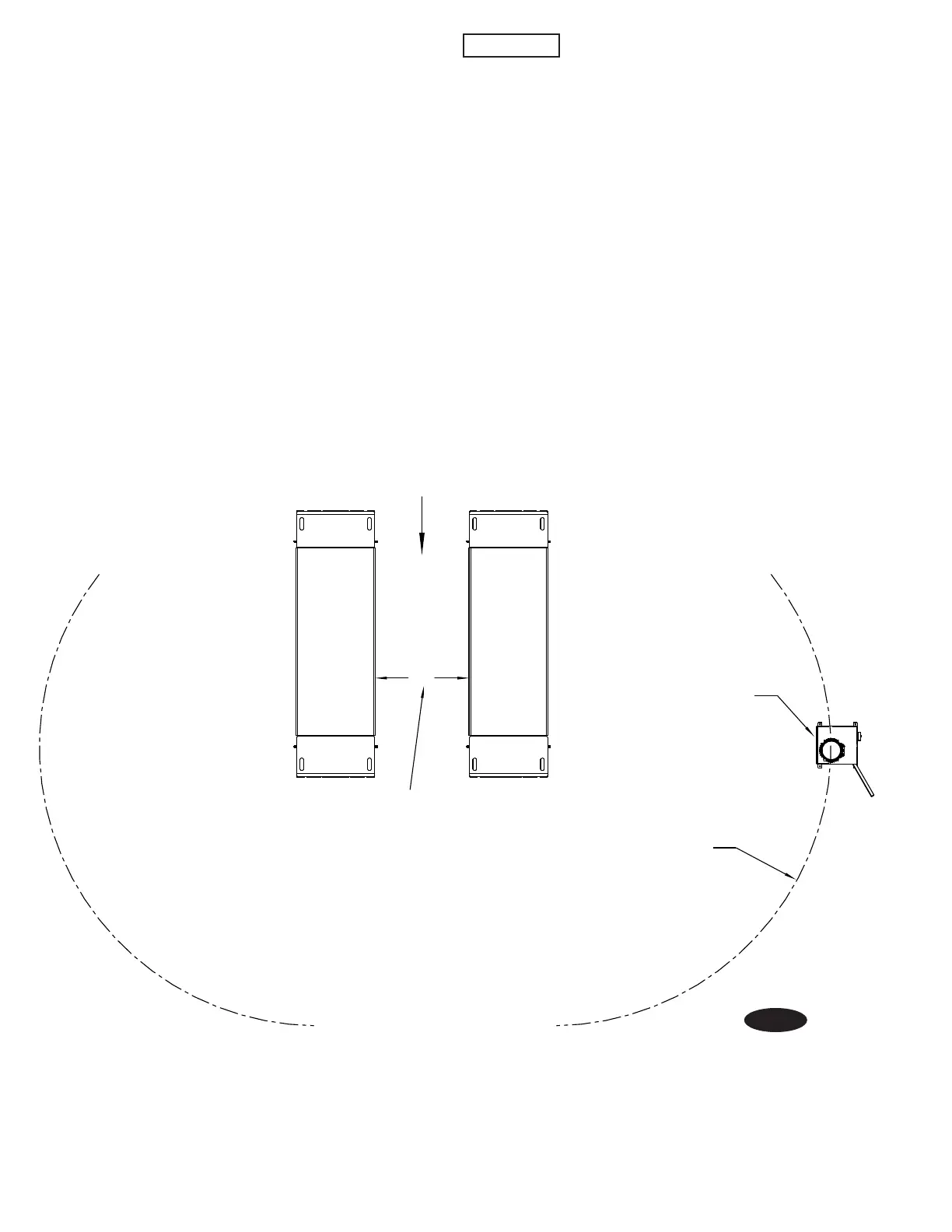
9. Platforms and Control Cabinet Detail Layout
Place platforms and control cabinet as shown in Fig. 3
for surface mount or flush mount applications.
DO NOT anchor any components at this time. The
control cabinet should be located on the opposite
end of vehicle approach, as shown in Fig. 3. Operator
should be in a position to notice any misalignment of
lifting pads or vehicle during operation. Rotary Lift
does not recommend placing the control cabinet in a
different location orientation and doing so would be
the responsibility of the installer and/or end user.
*750
CONTROL CABINET PLACEMENT
DISTANCE BETWEEN
PLATFORMS
CONTROL CABINET SHOULD BE
ORIENTED SO THAT OPERATOR
FACES LIFT WHEN OPERATING
CONTROLS
DIRECTION
OF APPROACH
CONTROL CABINET PLACEMENT ENVELOPE
MAXIMUM 5 METERS FROM EDGE OF LIFT PLATFORM,
MINIMUM 1.5 METERS FROM EDGE OF LIFT PLATFORM,
EITHER FRONT SIDE OF LIFT (HOSE SIDE)
(OPTIONS AVAILABLE FOR HOSE EXTENSIONS
AND ADDITIONAL HOSE COVERS IF EXCEED
5 METERS ENVELOPE)
*NOTE: 750mm WILL ACCOMMODATE MOST
VEHICLES. LIFT MAY BE ADJUSTED DURING
INSTALLATION BUT DISTANCE BETWEEN
PLATFORMS SHOULD NOT EXCEED 912mm.
Fig. 3
IMPORTANT
Control cabinet should always be
oriented so operator is facing the direction of the lift
when operating the lift.
If lift will be a flush mount application, the total run
length of the pipe chase from pit to bottom rear of
control cabinet should not exceed 2000mm.
10
 Loading...