3
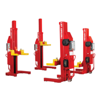
Power Unit Tank
Battery Locations
M20 Bolt
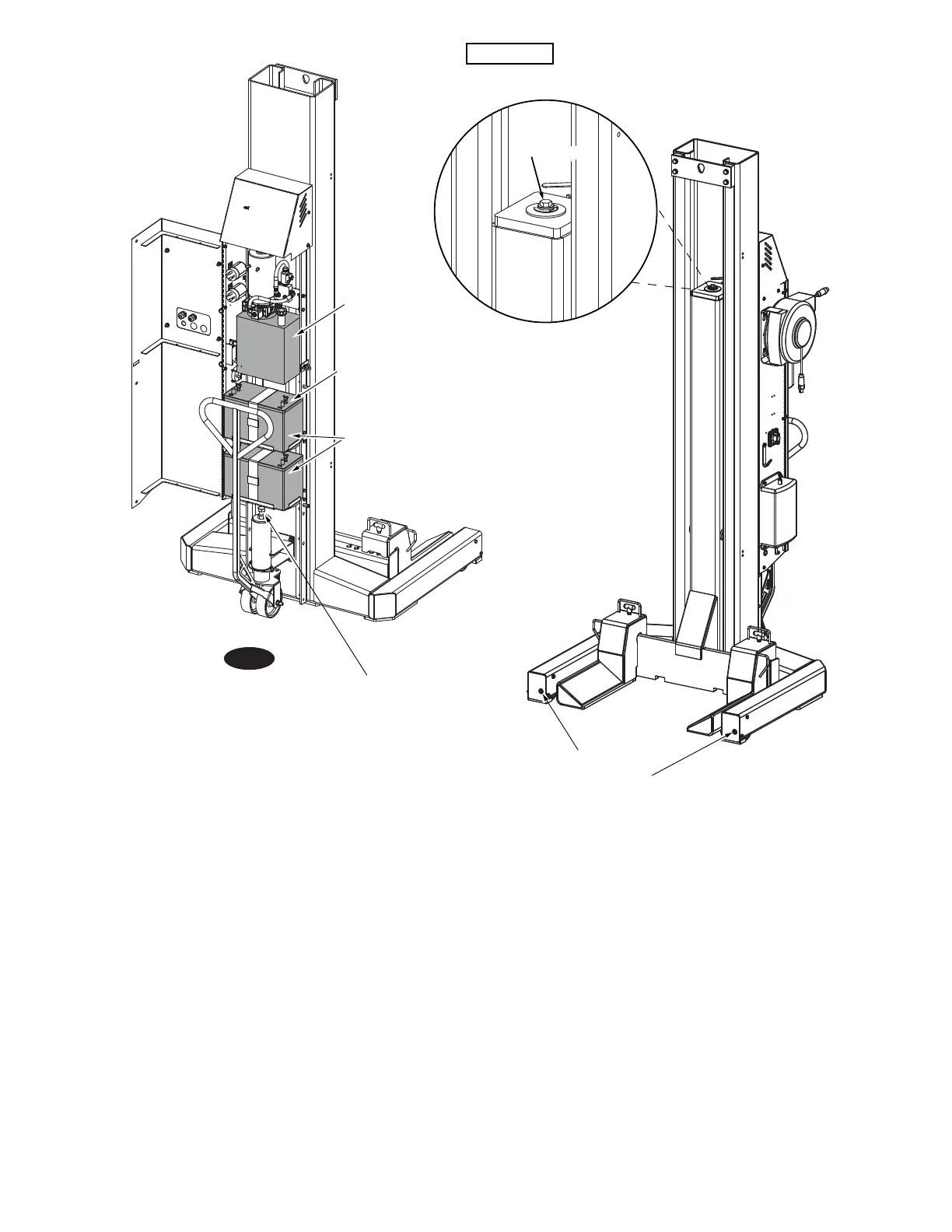
Adjust For
Ground
Clearance
M10
Socket Head
Adjust For
Ground
Clearance
IMPORTANT! Negative
Post Must Be Located
On This Side
Bleed Screw
Do Not Exceed Torque Values
On Bleeder Screw
Torque Values: 177-230 In/Lbs (20Nm-26Nm)
IMPORTANT
Fig. 1
DO NOT use on asphalt. Lift must be on concrete
with a minimum strength of 3000PSI and a minimum
thickness of 4.5”. Maximum allowed floor slope is 1/8”
per foot side to side of vehicle and 1/4" per foot front
to rear of vehicle. DO NOT use on a suspended floor
structure without specific approval from structural
engineer.
Upon completion of the assembly of the lift, the lift is
to be operated to assure proper function. Observe for
locks operating in all locking positions, each side lifts
equally, hydraulics do not leak, all electrical controls
function as labeled, all pneumatics are functional
and leak free, ramps rotate freely (if applicable), and
proper clearances with all items in bay have been
maintained.
Operate the lift with a typical vehicle and observe to
assure the same items for proper functioning.
Ensure tires are properly inflated before lifting. DO
NOT exceed tire load rating when raising vehicle.
DO NOT raise/lower only one side of a vehicle.
Lift only on same axle. DO NOT stagger between
axles.
DO NOT drive over or pinch electrical cables.
 Loading...