5
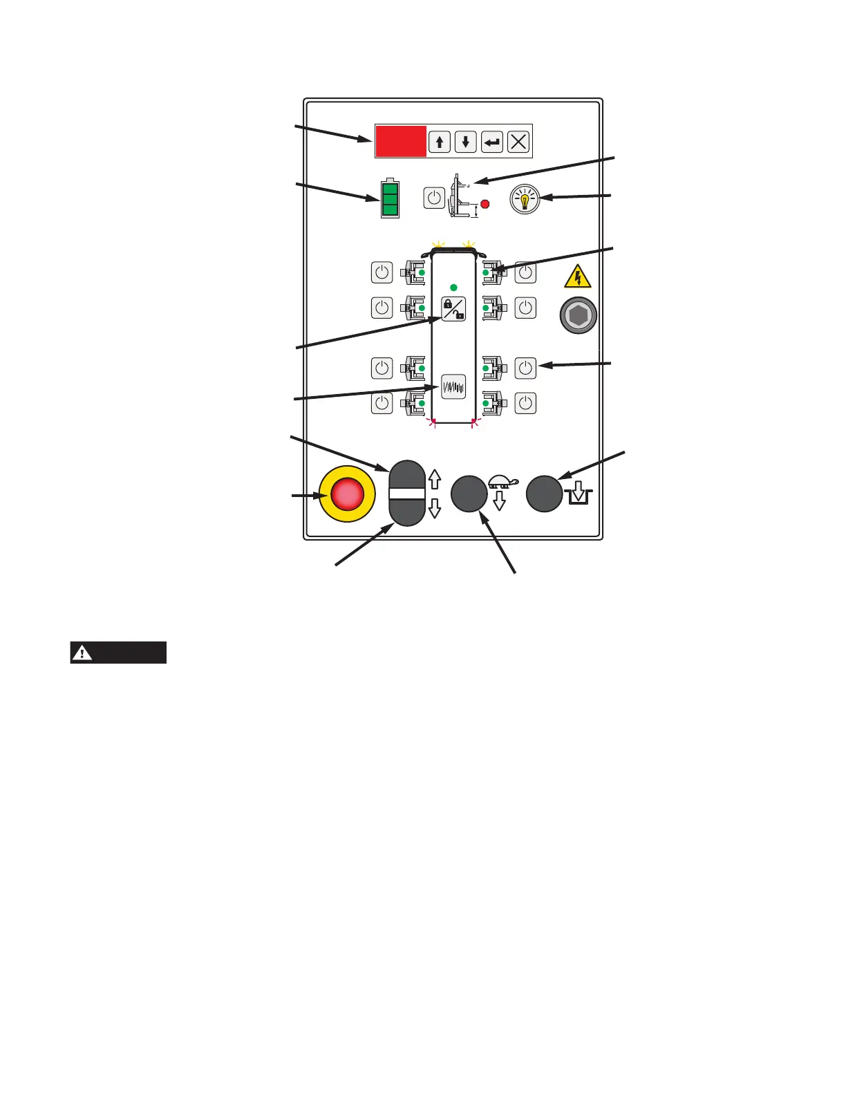
Lights on/off
(Optional Accessory)
Activate Column Buttons
(8 Total)
Lower To Locks
Height Limit Setting
System Configuration
Lock/Unlock
Single/Pair/All Mode
E-Stop
Raise
Lower
Yellow, Green, Red
Activation LED’s
(8 Total)
Data Information
Display and Buttons
Quick Start Operating Instructions
Control Panel Diagram
1. The service area must be clear of all personnel before
the vehicle is positioned.
Locate lift on level concrete surface with a
minimum strength of 3000 psi.
2. Spotting: Position the vehicle in the location where it is
to be lifted.
Note: See Fig. 2 for the general arrangement of each lift
column.
3. Loading:
Position one column at a lifting wheel location. Position
so that the forks are under the tire and the unit is pushed
in as far as possible, Fig. 3. Ensure fork width is adjusted
to properly accommodate the tire/wheel size. Turn on the
Power Up Switch, Fig. 4.
4. Using the Control Panel and the bus diagram as a
reference (see graphic above), press the Activate Column
Button relative to the location where the column was just
placed. The column will show Green when activated.
5. Plug the fixed length communication cable from the cord
reel into the bottom of the control panel.
6. Position next column at second wheel using loading
instructions from step 3.
7. Run the reel-end of the communication cable from the
first column and plug into the side of the control panel on
the second column. Turn on second column. Again, using
the Control Panel and the bus diagram as a reference, press
the Activate Lift Button relative to the location of the second
column. The lift will show Green when activated. The first
lift you activated should now be flashing yellow on your
control panel.
8. Repeat step 5 thru 7 for remaining columns. When
the entire system of columns is complete, press the
System Configuration Lock/Unlock button to lock the lift
configuration for operation.
NOTE: The electrical communication cables do not
have to make a complete loop. You do not have to plug
the last lift back into the first lift.
 Loading...