Section 03 787 RFI ENGINE
Subsection 04 (BOTTOM END)
F12R18A
Do not apply in excess as it will spread out inside
crankcase.
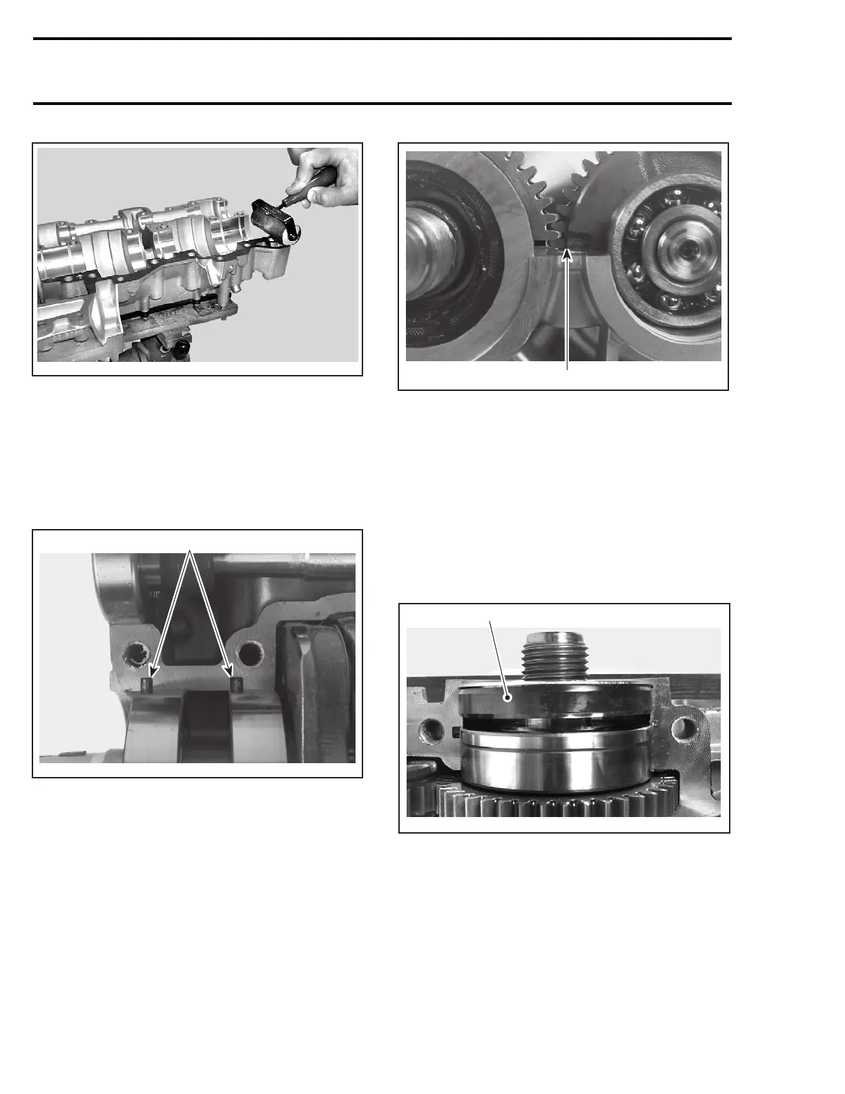
Crankshaft and Counterbalance Shaft
Install crankshaft no. 3 in crankcase.
NOTE: When installing crankshaft in crankcase,
make sure drive pins no. 6 of bearings are properly
installed in crankcase recesses.
F00D0OA
1
1. Drive pins
After crankshaft installation, install counterbal-
ance shaft no. 13. Make sure to properly index
crankshaft and counterbalance shaft by gear align-
ing marks.
CAUTION: Marks on the crankshaft and coun-
terbalance shaft must be aligned, otherwise en-
gine will vibrate and premature wear will occur.
F00D0PA
1
1. Marks must be aligned
Turn by hand the crankshaft and counterbalance
shaft. Make sure they do not interfere with the
crankcase.
PTO Crankshaft Seal
When installing seal no. 5, apply a light coat of
lithium grease on seal lips.
Position PTO seal against the retaining shim; the
gap between the seal no. 5 and bearing no. 4 will
ensure proper lubrication of the bearing.
F00D0NA
1
1. Seal against the retaining shim
Counterbalance Shaft Bearing Cover
Install the bearing cover no. 19 with its hollow side
toward the bearing.
98 smr2005-083
 Loading...