Section 01 ENGINE MEASUREMENT
Subsection 01 (MEASUREMENT PROCEDURES)
Remove cover then clean and measure com-
pressed soldering wire thickness, it must be
within the specified tolerance.
If rotary valve cover clearance is over specified tol-
erances, machine rotary valve cover seating sur-
face or replace the cover.
Machining the Rotary Valve Cover
The amount of material over tolerance must be
removed from the rotary valve cover seating sur-
face.
Also cut the O-ring groove the same amount to
keep the 1.00 ± 0.03 mm (.039 ± .001 in) depth
between the bottom of the groove and the seating
surface.
Remove burrs on the edges of the seating surface
andO-ringgroove.
1
A
F01D3OA
SAME AMOUNT REMOVED FROM COVER SEATING
SURFACE AND O-RING GROOVE BASE
1. Cover seating surface
A. O-ring groove depth must be 1.00 ± 0.03 mm (.039 ± .001 in)
Reverify the clearance.
At assembly, the rotary valve timing must remain
as per original setting.
NOTE: If rotary valve crankcase surface is worn, it
is possible to have it reworked at the factory.
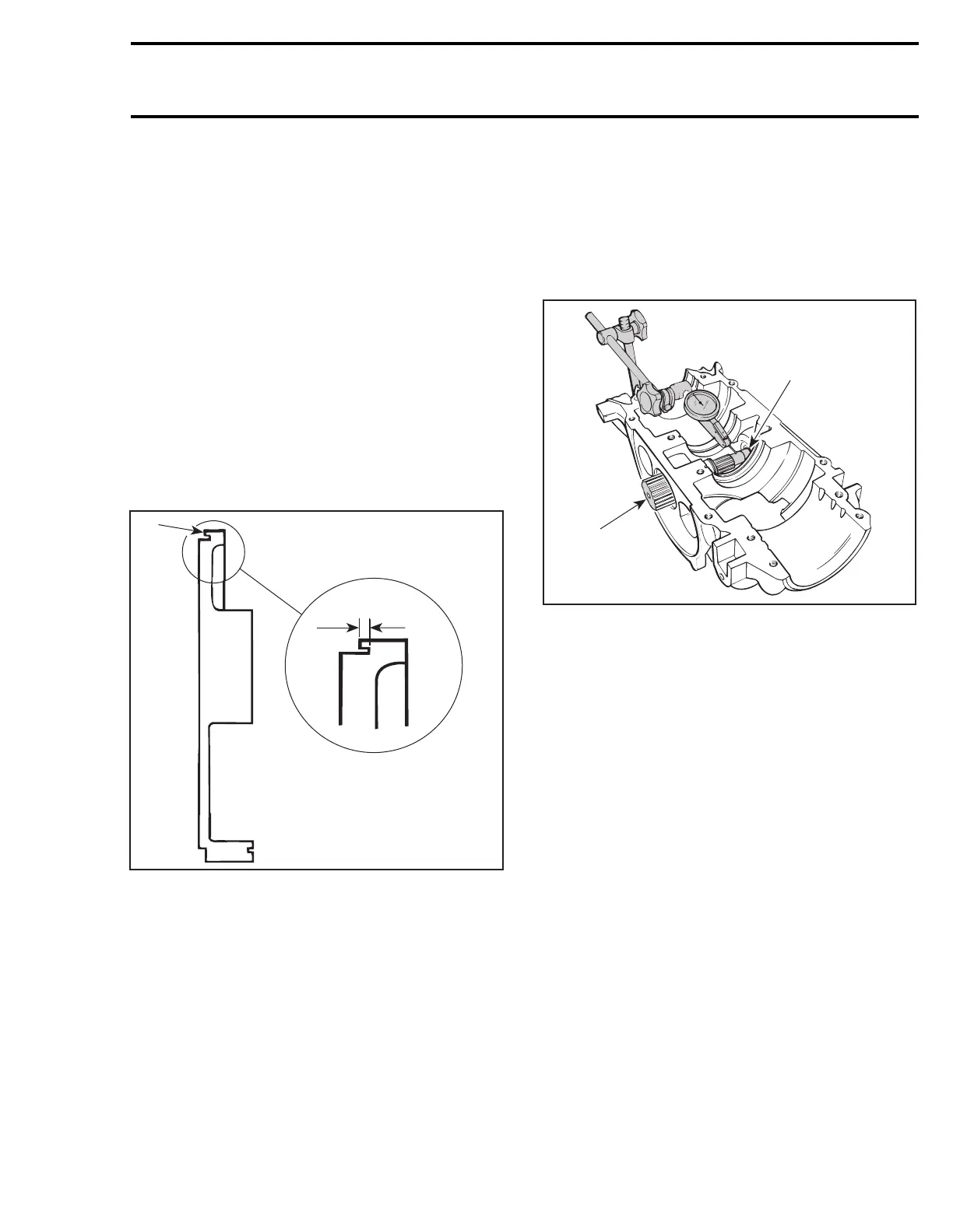
Rotary Valve Shaft Deflection
Deflection is measured with a dial gauge. Install
rotary valve shaft in crankcase half, without its
gear.
NOTE: End bearing must be in crankcase half.
Measure shaft deflection next to gear splines.
F01D2CA
2
1
1. Rotary valve shaft
2. End bearing in place
If the deflection of rotary valve shaft exceeds the
specified tolerance, replace it.
smr2005-085 9
 Loading...