SMART WiFi modem for LCAC units
7User manual
PART 3. INSTALLATION AND CONFIGURATION
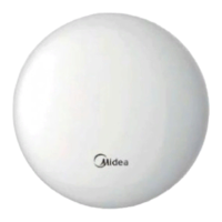
2.2. Wiring principle sketch:
red
black
yellow
brown
red
black
yellow
brown
Applicable to WF-60A1 only
Applicable to WF-60A1 only
Wi control box
4-Core Shield Cable, the length is decided
by installation
Fig. 2.2
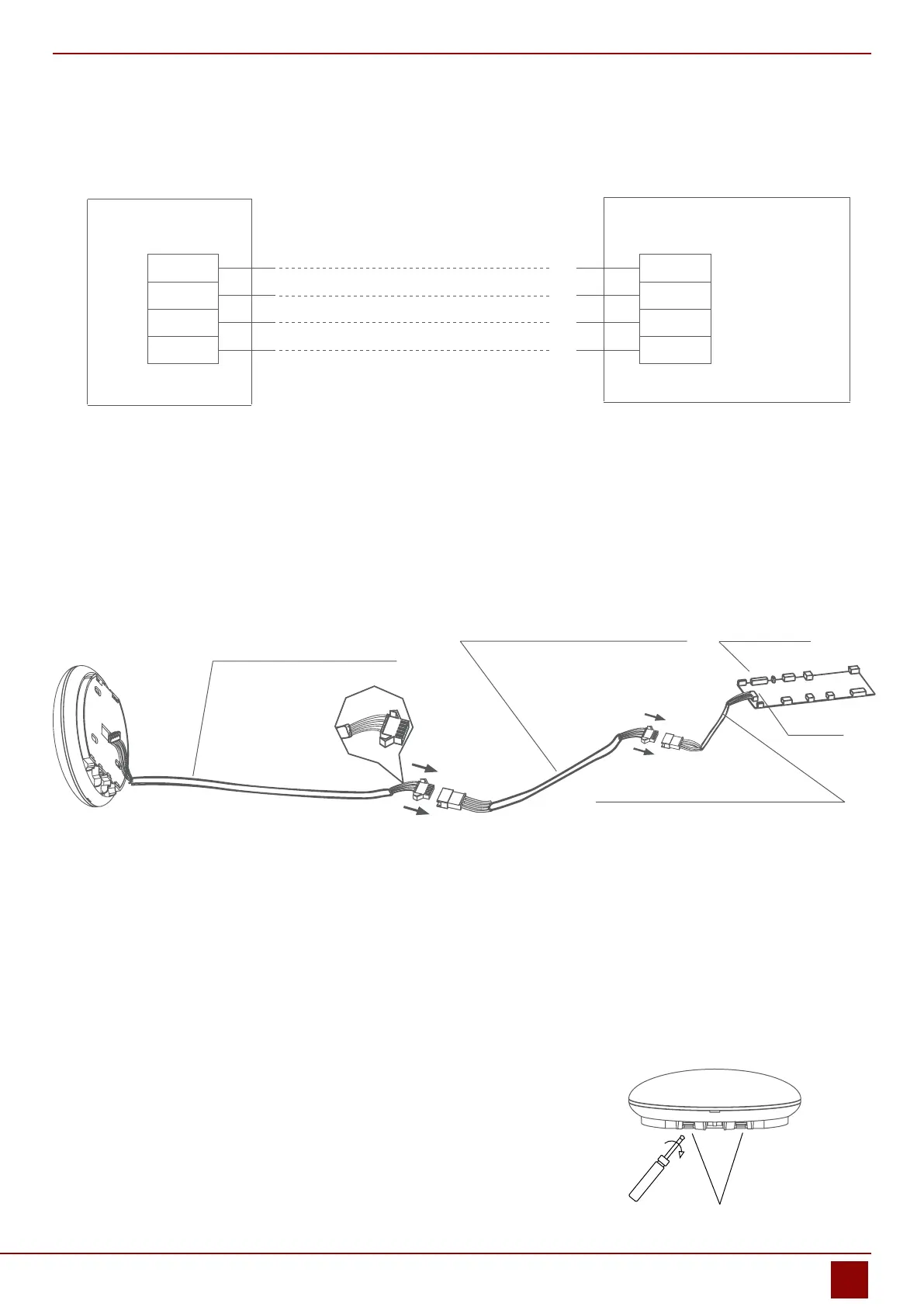
2.3. Wiring gure
• Connect the male joint of the connective wires group-1 to the mainboard then connect the other side of the
connective wires group-1 to the 4-core shielding wire of the smart port. (See Fig.2.3)
• If want to extent the wire ,please use extension cord (purchased separately) . (See Fig.2.3)
4-core shielding wire
Extension cord (purchased separately) Mainboard
The connective wires group-1
CN40
Fig. 2.3
2.4. Remove the upper part of the smart port
• Insert a slot screwdriver into the slots in the lower part of the
smart port (2 places), and remove the upper part of the smart
port. (Fig.2.4)
Slots
Fig. 2.4
 Loading...