the body and trunking, disconnect the hot air
intake tube, and release the trunking from the
connecting duct at the front of the car.
Remove the air cleaner body and trunking.
6 If the cold air side intake is to be removed,
refer to Chapter 5, and remove the battery.
7 Undo the bolt securing the side intake to
the body, and remove the intake and duct
(see illustration).
Refitting
8 Refitting is a reversal of removal, but ensure
that all the ducts and trunking are fully
engaged before tightening the various
retaining bolts.
3 Accelerator cable - removal,
refitting and adjustment
4
Removal
1 Refer to Section 2 and remove the air
cleaner air box.
2 Unscrew the accelerator cable locknut
nearest to the cable end, pull the outer cable
upwards, and slide the inner cable out of the
slot in the support bracket (see illustration).
3 Release the inner cable end from the slot in
the throttle cam (see illustration).
4 From inside the car, release the turnbuckles
and lift out the trim panel over the clutch,
brake and accelerator pedals.
5 Prise the retaining clip from the top of the
accelerator pedal, and disconnect the inner
cable.
6 Release the cable from the engine
compartment bulkhead and from the support
clips, and withdraw the complete cable from
the car.
Refitting and adjustment
7 Refitting is a reversal of removal. Adjust the
cable initially by means of the outer cable
locknuts, to give a small amount of free play
with the throttle closed. On completion, check
the base idle speed as described in Sec-
tion 11.
4 Accelerator pedal -
removal and refitting
1
Removal
1 From inside the car, release the turnbuckles
and lift out the trim panel over the clutch,
brake and accelerator pedals.
2 Prise the retaining clip from the top of the
accelerator pedal, and disconnect the inner
cable from the pedal arm.
3 Undo the bolts securing the pedal bracket
to the bulkhead, and withdraw the bracket
and pedal assembly (see illustration).
4 Disconnect the switch wiring and remove
the bracket and pedal.
5 If the accelerator pedal switch is to be
removed, prise off the retaining C-clip and
remove the switch and washer.
Refitting
6 Refitting is a reversal of removal.
5 Fuel system -
depressurisation
1
Warning: Refer to the
precautions contained in
Section 1 before proceeding.
1 The fuel system referred to in this Chapter is
defined as the fuel tank and tank-mounted fuel
pump/fuel gauge sender unit, the fuel filter, the
throttle body, and the metal pipes and flexible
hoses of the fuel lines between these
components. Most of these contain fuel which
will be under pressure while the engine is
running and/or while the ignition is switched on.
2 The pressure will remain for some time after
the ignition has been switched off, and must
be relieved before any of these components
are disturbed for servicing or repair work.
3 Disconnect the battery negative (earth) lead
(refer to Chapter 5, Section 1).
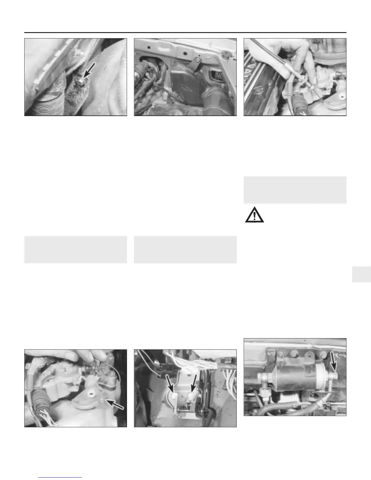
4 Place absorbent rags around the fuel filter
outlet union banjo bolt, then slowly unscrew
the bolt to release the pressure (see
illustration).
Fuel and exhaust systems - single-point injection engines 4A•3
3.2 Undo the accelerator cable locknut . . .2.7 Side intake to body retaining bolt
(arrowed)
2.5c . . . and the air cleaner trunking to
support bracket bolt (arrowed)
5.4 Place absorbent rags around the fuel
filter outlet union banjo bolt (arrowed),
then slowly unscrew the bolt to release the
system pressure
4.3 Accelerator pedal bracket retaining
bolts (arrowed)
3.3 . . . and release the cable end
(arrowed) from the throttle cam
4A
1380 Rover 800 Series Remake


 To Next Page
 Loading...
