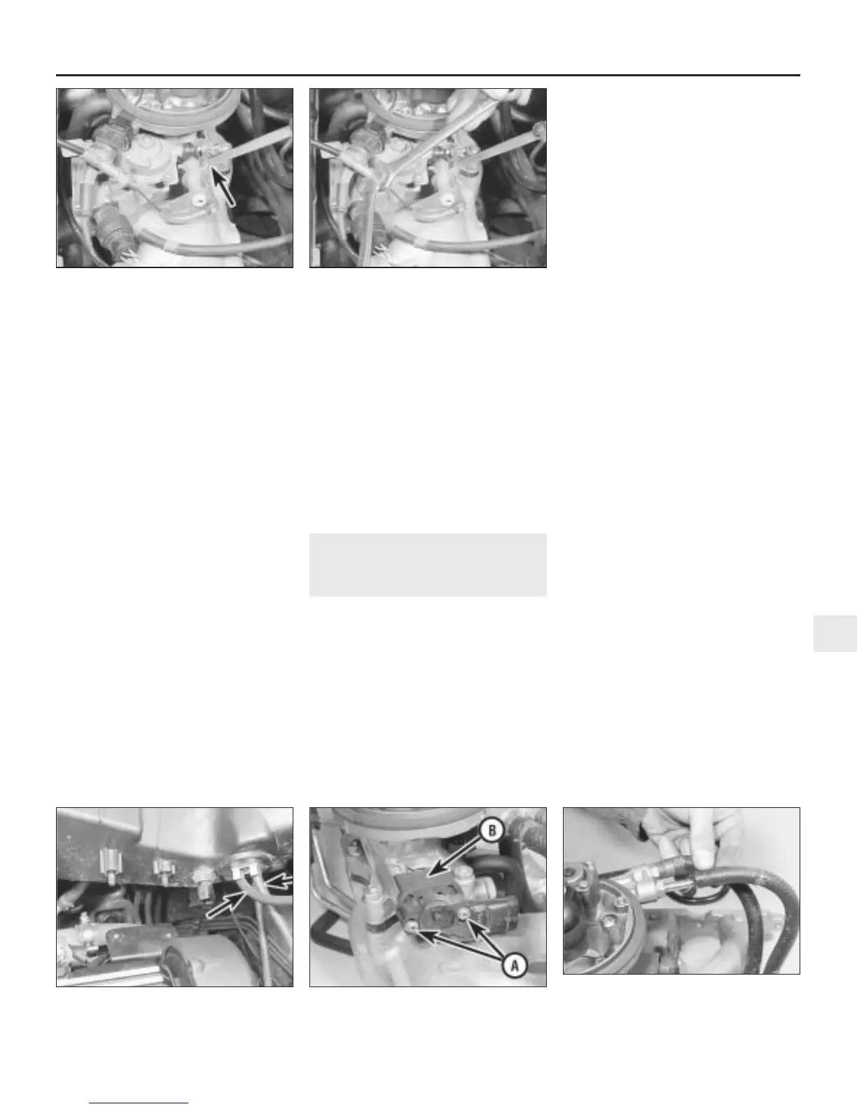
16 Check the lost motion gap by inserting a
feeler gauge of the specified size between the
forked end of the throttle lever and the peg on
the linkage. If the gap requires adjustment,
slacken the accelerator cable locknuts and
reposition the outer cable until the correct
setting is achieved (see illustrations). Tighten
the locknuts when the gap is correct.
17 Reconnect the stepper motor multiplug.
18 Switch off the ignition, wait three seconds
and switch the ignition on once more. After a
further three seconds, switch off the ignition
again. The stepper motor will now be in the
correct position for the next engine start.
19 On cars equipped with automatic
transmission, refer to Chapter 7, Part B and
check the kickdown cable adjustment.
20 Refit the air cleaner air box and
disconnect the tachometer on completion.
Electronic control unit calibration
21 As previously stated, whenever the
battery is disconnected, the idle mixture
setting stored in the ECU memory will be lost.
On reconnection of the battery, the following
procedure may be used to recalibrate the unit
temporarily, until such time as the car can be
taken to a dealer for accurate setting on Rover
dedicated test equipment.
22 Run the engine with all electrical circuits
switched off, until the engine cooling fan
operates then stops.
23 Switch off the engine immediately the
cooling fan stops.
24 Switch the ignition on to position two of
the key.
25 Depress the accelerator pedal through at
least half its travel, then release it, five times.
26 Wait until the high engine temperature
warning light starts to flash.
27 As soon as the high engine temperature
warning light stops flashing, start the engine
without depressing the accelerator pedal,
and allow it to idle. If the accelerator pedal is
depressed, or if an electrical unit is switched
on, the calibration will cease. (This also
applies to the interior lights operated by the
door pillar switches, so keep the doors
closed).
28 Wait for two to three minutes until the
warning light flashes again, indicating that
calibration is complete.
12 Fuel injection system
components -
removal and refitting
3
Note: Refer to the precautions contained in
Section 1 before proceeding.
Thermac switch
Removal
1 Refer to Section 2 and remove the air
cleaner air box.
2 Disconnect the two vacuum hoses at the
thermac switch on the base of the air box (see
illustration).
3 Remove the air box intake trunking for
access to the switch.
4 Carefully prise off the switch retaining clip,
and remove the switch from inside the air box.
Refitting
5 Refitting is a reversal of removal, but
position the unit so that the large diameter
pipe is towards the air temperature sensor.
Connect the vacuum hose from the manifold
to the pipe with the small diameter hole, and
the vacuum hose from the air cleaner vacuum
motor to the pipe with the large diameter hole.
Inlet air temperature sensor
Removal
6 Refer to Section 2 and remove the air
cleaner air box.
7 Unscrew the sensor from the adaptor on
the base of the air box. If the adaptor
unscrews with the sensor, unscrew the
adaptor and refit it to the air box.
Refitting
8 Refit the sensor to the adaptor, and refit the
air box.
Throttle potentiometer
Removal
9 Refer to Section 2 and remove the air
cleaner air box.
10 Disconnect the multiplug from the side of
the potentiometer body.
11 Using a dab of paint, mark the position of
the throttle potentiometer in relation to the
mounting adaptor.
12 Undo the two screws, remove the
potentiometer, and lift off the adaptor (see
illustration).
Refitting
13 Refitting is a reversal of removal. Ensure that
the potentiometer lever engages to the right of
the throttle lever, and align the previously-made
mark before tightening the retaining screws.
Have the potentiometer position adjusted
accurately by a Rover dealer on completion.
Injector housing
Removal
14 Relieve the fuel system pressure as
described in Section 5.
15 Refer to Section 2 and remove the air
cleaner air box.
16 Using pliers, release the two fuel hose
retaining clips at the injector housing, and
disconnect the two hoses (see illustration).
Plug the hoses after removal.
Fuel and exhaust systems - single-point injection engines 4A•7
12.2 Thermac switch vacuum hoses
(arrowed)
11.16b . . . and adjust the lost motion gap
at the accelerator cable
11.16a Insert a feeler gauge between the
throttle lever and peg . . .
12.16 Release the two fuel hose retaining
clips at the injector housing, and
disconnect the two hoses
12.12 Throttle potentiometer retaining
screws (A) and adaptor (B)
4A
1380 Rover 800 Series Remake


 To Next Page
 Loading...
