during warm-up conditions, is fitted to the
underside of the inlet manifold. The heater is
of the positive temperature coefficient (PTC)
type, in which the current consumption of the
heating element is high while it heats up, but
is greatly reduced at operating temperature.
The unit is controlled by a temperature
sensor, screwed into the coolant jacket of the
inlet manifold. When coolant temperature
reaches 50ºC, the sensor switches the
manifold heater off. To avoid a heavy drain on
the battery, current for the heater is supplied
via the oil pressure switch relay, and
consequently only switches on after the
engine has started.
Fuel pressure regulator: The fuel pressure
regulator is attached to the throttle body, and
maintains fuel pressure at a constant 1.0 bar.
When the pressure exceeds this value, the
regulator returns excess fuel to the tank via
the fuel return line.
Inertia switch: An inertia switch is fitted in
the ignition switch feed to the fuel pump relay,
and is situated inside the car behind the left-
hand side of the radio cassette player. In the
event of sudden impact, the switch trips out,
thus switching off the fuel pump relay. The
switch can be reset by pressing down the
reset button on the switch body.
Relays: The main fuel system relay is
energised when the ignition is switched on,
and supplies current to the ignition coil and
the fuel system ECU. The relay remains
energised for approximately five seconds after
the ignition is switched off, to enable the
stepper motor to cycle to the correct position
for engine starting. The fuel pump relay is
energised when the oil pressure relay is de-
energised by the low oil pressure switch.
When the engine is cranking, the fuel pump is
fed from the starter solenoid via the de-
energised fuel pump relay.
Fuel pump: The fuel pump is a self-priming
centrifugal unit, located in the fuel tank, and
totally submerged in the fuel. Fuel is supplied
under pressure from the pump, through a
non-return valve and in-line filter, to the fuel
pressure regulator, and then to the fuel
injector. The high capacity output of the pump
is reduced by a resistive wire in the harness
which reduces the supply voltage.
Accelerator pedal switch: When the
accelerator pedal is at rest, the pedal switch is
closed, and a signal is sent to the ECU
indicating that the engine is idling. On receipt
of this information, the ECU selects the idle
program from its memory, and automatic idle
speed control via the stepper motor is
implemented.
11 Fuel injection system -
testing and adjustment
4
Testing
1 If a fault appears in the fuel injection
system, first ensure that all the system wiring
connectors are securely connected and free
of corrosion. Then ensure that the fault is not
due to poor maintenance; ie, check that the
air cleaner filter element is clean, the spark
plugs are in good condition and correctly
gapped, the cylinder compression pressures
are correct, and that the engine breather
hoses are clear and undamaged, referring to
the relevant Sections of this Chapter, and to
Chapters 1 and 2 for further information.
2 If these checks fail to reveal the cause of
the problem, the vehicle should be taken to a
suitably equipped Rover dealer for testing on
Rover dedicated test equipment. This
equipment will locate the fault quickly and
simply, alleviating the need to test all the
system components individually, which is a
time-consuming operation that carries an
element of risk of damaging the ECU.
Adjustment
Engine tuning procedure
3 Before making any changes to the settings
of the fuel injection system, ensure that the
spark plug gaps are correctly set, the air
cleaner element is clean, there are no leaks in
the exhaust system, and the ignition system is
operating correctly. Ensure that all breather
and vacuum hoses are connected, and that
none are perished or kinked.
4 Temperature effects, and engine and
transmission oil drag, can adversely influence
the base idle speed setting, and it is important
that the following warm-up procedure is
adopted before attempting any adjustments.
5 Drive the car on the road for approximately
two to four miles, dependent on summer or
winter conditions, in a normal manner, without
excessive load, engine speed or road speed.
6 Return the car to the working area, switch
off and connect a tachometer, following the
equipment manufacturer’s instructions.
7 Start the engine again, and run it at
2000 rpm for ten seconds to stabilise the
mixture. The adjustment procedure described
in the following paragraphs can now
commence. If during the procedure the
cooling fan operates, or if adjustment is not
completed within two minutes, accelerate the
engine to 2000 rpm again, by means of the
throttle linkage (not the accelerator pedal) and
hold this speed for a further ten seconds.
Repeat this every two minutes until the
adjustments are completed.
Base idle speed and mixture
adjustment
8 The function of the fuel injection system is
such that the base idle speed and idle mixture
settings are controlled by the ECU, and of
these two, only the base idle speed can be
adjusted without the use of the
manufacturer’s test equipment. Should poor
idle quality be experienced, the base idle
speed should be checked, and if necessary
adjusted, using the following procedure. The
idle mixture setting will not normally require
attention unless the battery is disconnected,
in which case the settings in the ECU memory
will be lost. If the battery is disconnected for
any reason, the ECU can be recalibrated
using the procedure described in para-
graphs 21 to 28 as a temporary measure.
9 Refer to the engine tuning procedure above
before starting.
10 Switch off the engine, and ensure also
that all electrical circuits are switched off
throughout the procedure.
11 Undo the five bolts and lift off the air
cleaner box. Place the air box alongside the
engine, without disconnecting any of the
hoses or ducts.
12 Operate the throttle by hand, and check
that it opens fully and returns to rest against
the stepper motor pushrod.
13 Start the engine and using the throttle
linkage, not the accelerator pedal, increase
the engine speed to 1200 rpm, and hold it at
this speed. Check that the stepper motor
pushrod has retracted fully, then disconnect
the stepper motor multiplug (the round plug
on the side of the throttle body below the
accelerator cable).
14 Release the throttle and allow the engine
to stabilise at idle speed.
15 Check the engine base idle speed on the
tachometer, and compare the reading with the
figure given in the Specifications. If
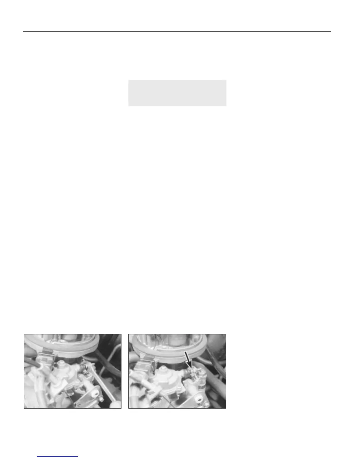
adjustment is required, slacken the adjusting
screw locknut and turn the adjusting screw as
necessary to obtain the correct setting (see
illustrations). Tighten the locknut when the
speed is correct.
4A•6 Fuel and exhaust systems - single-point injection engines
11.15b . . . and turn the adjusting screw
(arrowed) to obtain the correct setting
11.15a Slacken the base idle speed
adjusting screw locknut . . .
1380 Rover 800 Series Remake


 To Next Page
 Loading...
