consult one of the motoring organisations (or a
similar authority) for advice on the petrols
available and their suitability for your vehicle.
1 The fuel recommended by Rover is given in
the Specifications at the beginning of this
Chapter, followed by the equivalent petrol
currently on sale in the UK.
2 RON and MON are different testing
standards.; RON stands for Research Octane
Number (also written as RM), while MON
stands for Motor Octane Number (also written
as MN).
3 All non-catalyst equipped 4-cylinder engine
models covered by this manual are designed
to run on leaded or unleaded petrols without
modification. Only unleaded petrol may be
used in those models fitted with a catalytic
converter.
10 Fuel injection system -
general information
The single-point fuel injection (SPi) system
is a microprocessor-controlled fuel
management system, designed to overcome
the limitations associated with conventional
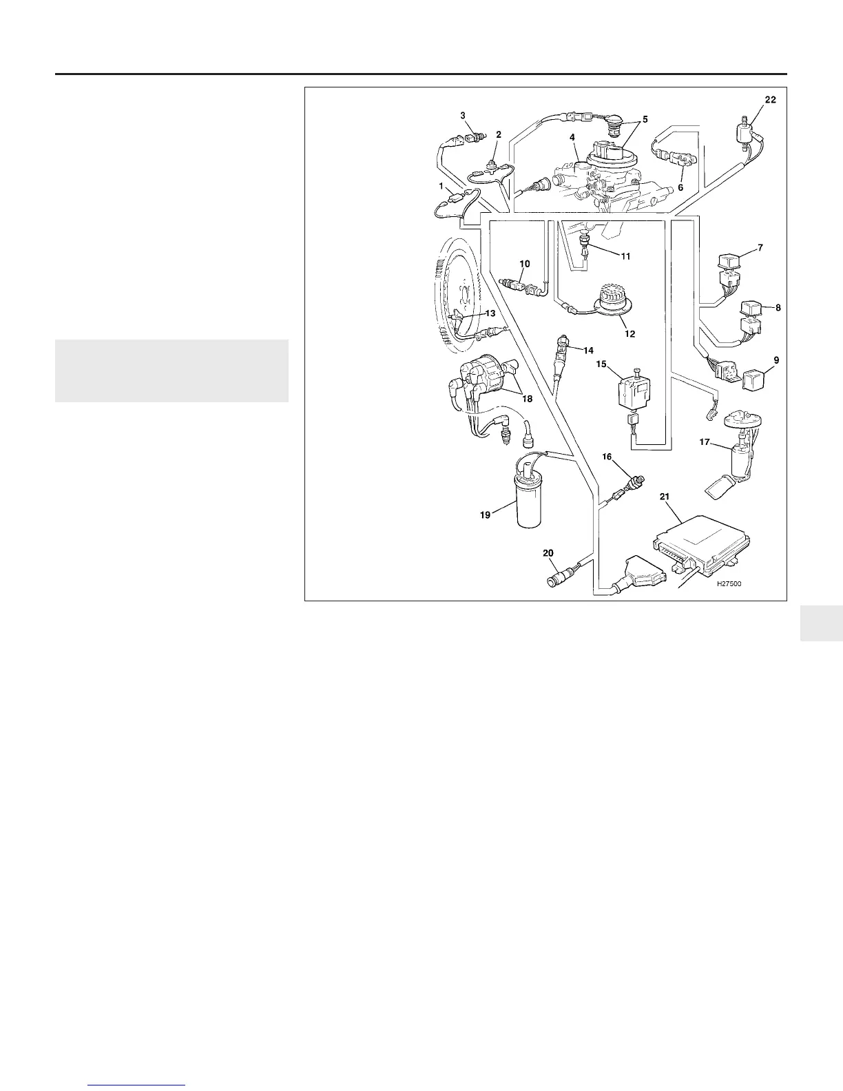
carburettor induction (see illustration). This is
achieved by continuously monitoring the
engine using various sensors, whose data is
input to the fuel system Electronic Control
Unit (ECU). Based on this information, the
ECU program and memory then determine the
exact amount of fuel necessary, which is
injected into the throttle body by a single
injector, for all actual and anticipated driving
conditions.
The main components of the system and
their individual operation is as follows.
Fuel/ignition ECU: The fuel ECU is a
microprocessor which controls the injector
opening time, and therefore the amount of fuel
supplied. Contained in the ECU memory is a
program from which a pulse is derived, the
length of which determines the fuel injector
opening duration. Information received from
the various engine sensors will cause the ECU
to alter the fuel requirements, by changing the
pulse length. Airflow measurement is based
on the speed/density method, in which the
inlet air temperature and inlet manifold
pressure are measured under the assumption
that the engine is a calibrated vacuum pump,
with its characteristics stored in the ECU
memory. The air/fuel ratio requirements for all
engine speeds and loads are also stored in
the ECU. This information on the engine’s
basic fuel requirements is constantly
amended, according to the information
received from the various sensors. In addition
to this, the engine idle speed is also controlled
by the ECU, which uses a stepper motor to
open or close the throttle as required. Two
separate programs control the ECU functions.
One program operates under cruise
conditions, and the other at idle. The idle
program can be altered completely using
electronic test equipment, or partially by using
the procedures described in Section 11. Any
changes to this program do not affect the
cruise program, which cannot be accessed.
Whenever the battery is disconnected, the
idle program is lost, and the ECU reverts back
to a set of nominal parameters until the
information is reintroduced into the memory.
This can only be done using the
manufacturer’s test equipment, but the
performance of the engine at idle is only
marginally affected in this condition. As well
as control of the fuel injection system, the
ECU is also used to control the ignition timing.
Fuel injector: The single fuel injector is a
solenoid-operated ball valve, containing a fine
gauze filter and a nozzle with six spray holes
for complete fuel atomization. When a pulse is
received from the ECU, the injector sprays
fuel into the air stream through the throttle
body.
Throttle potentiometer: The potentiometer
is a variable resistor, attached to the throttle
shaft on the throttle body. The unit is supplied
with a constant input voltage, and as the
resistance of the potentiometer varies with
throttle shaft movement, the output voltage is
proportionally affected. This allows the ECU
to determine throttle valve position, and rate
of change.
Idle speed stepper motor: This is a small
electric motor, having four control windings to
enable it to rotate in either direction. Under a
signal from the ECU, the stepper motor will
rotate in whichever direction is necessary, to
open or close the throttle by means of
pushrod acting directly against the base idle
speed adjusting screw.
Inlet air temperature sensor: Located in
the airflow through the air cleaner air box, the
sensor is a thermistor (resistive device whose
resistance quickly decreases with
temperature increase).
Coolant temperature sensor: This
resistive device is screwed into the thermostat
housing, where its element is in direct contact
with the engine coolant. Changes in coolant
temperature are detected by the ECU as a
change in the sensor resistance.
Ambient air temperature sensor: The
sensor is located behind the left-hand
headlight, and responds to changes in
ambient temperature with a corresponding
change in resistance.
Manifold heater: A manifold heater, to
improve atomization of the fuel/air mixture
Fuel and exhaust systems - single-point injection engines 4A•5
10.1 Main components of the single-point fuel injection system
4A
1380 Rover 800 Series Remake
1 Ambient air
temperature sensor
2 Accelerator pedal
switch
3 Inlet air
temperature sensor
4 Throttle body and
idle speed stepper
motor
5 Fuel injector and
fuel pressure
regulator
6 Throttle
potentiometer
7 Main fuel system
relay
8 Fuel pump relay
9 Oil pressure relay
10 Coolant
temperature sensor
11 Manifold heater
temperature sensor
12 Manifold heater
13 Crankshaft sensor
14 Knock sensor
15 Inertia switch
16 Oil pressure switch
17 Fuel pump
18 Distributor cap and rotor
arm
19 Ignition coil
20 Diagnostic plug connector
21 Fuel/ignition ECU
22 Idle solenoid (models with
air conditioning)


 To Next Page
 Loading...
