Resonator unit
Removal
51 Apply the handbrake, jack up the front of
the car and support it on axle stands.
52 Undo the two screws and one bolt
securing the access panel to the underside of
the front wheelarch on the left-hand side.
53 Disengage the access panel from the front
spoiler, and remove it from under the car.
54 Undo the two bolts and withdraw the
resonator from under the front wheelarch.
55 Remove the spacers and rubber
mountings from the resonator.
Refitting
56 Refitting is a reversal of removal.
Inertia switch
Removal
57 From inside the car, remove the stud from
the centre console side cover on the left-hand
side, and remove the cover.
58 Undo the two screws securing the inertia
switch to the mounting plate, disconnect the
wiring multiplug and remove the switch.
59 Check the operation of the switch by
striking the forward-facing side hard against
the palm of your hand. The setting button
should trip out when this is done. If not, renew
the switch.
Refitting
60 Refitting is a reversal of removal. Press
the button down to reset the switch after
installation.
Manifold heater
Removal
61 Disconnect the battery negative (earth)
lead (refer to Chapter 5, Section 1).
62 Refer to Section 2 and remove the air
cleaner air box.
63 Relieve the fuel system pressure as
described in Section 5.
64 Release the clips and disconnect the two
fuel hoses at the injector housing.
65 Disconnect the manifold heater wiring
connector.
66 Undo the two bolts securing the fuel pipe
clips and the heater to the manifold, and
move the pipes aside.
67 Undo the remaining heater retaining bolt.
68 Open the throttle fully, and remove the
heater by pushing down with a long
screwdriver through the throttle aperture.
69 Remove the O-ring and gasket from the
heater.
70 Clean the mating faces of the heater and
manifold, and renew the gasket and O-ring if
they show any sign of deterioration.
Refitting
71 Refitting is a reversal of removal.
13 Exhaust system - general
information and component
renewal
1
Warning: Inspection and repair
of exhaust system components
should be done only after
enough time has elapsed after
driving the vehicle to allow the system
components to cool completely. Also,
when working under the vehicle, make
sure it is securely supported on axle
stands.
General information
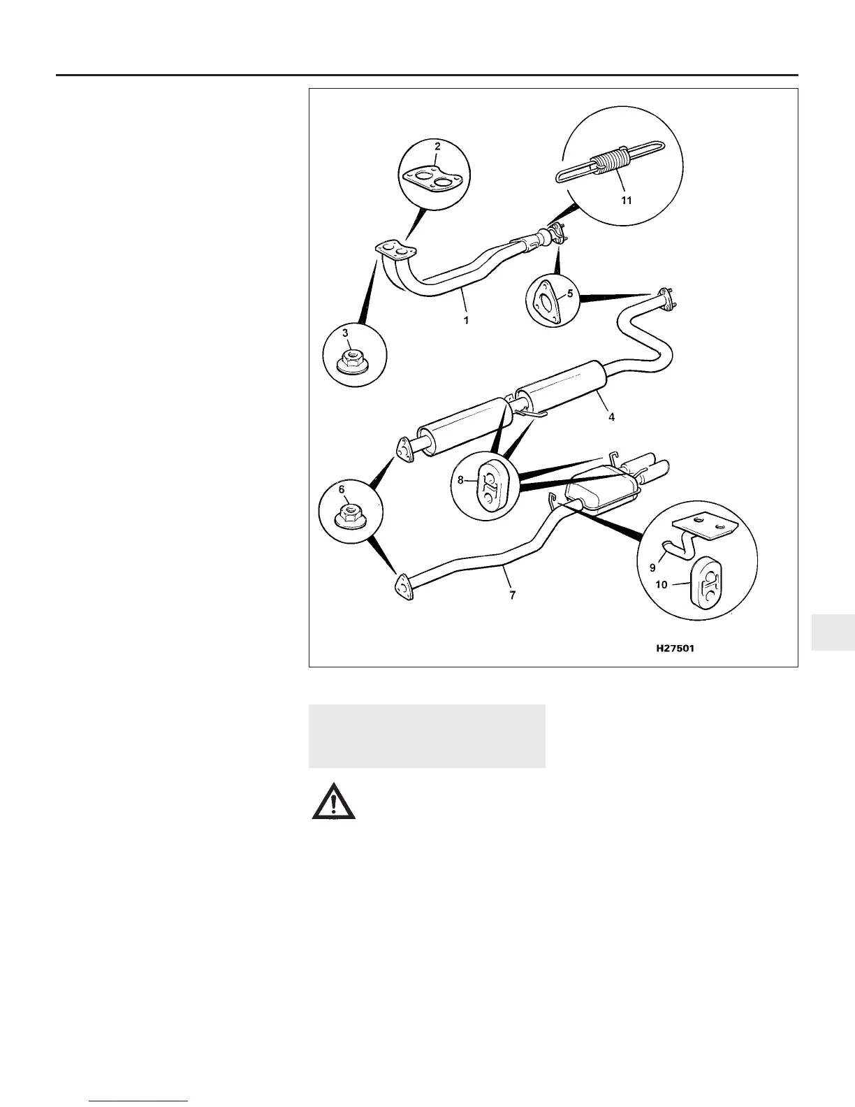
1 The exhaust system consists of a front,
intermediate and rear section, suspended
from the underbody on rubber mountings, and
bolted to a cast iron manifold at the front. A
ball-and-socket universal joint is incorporated
in the front section, to allow for engine
and exhaust system movement (see
illustration).
2 The exhaust system should be examined
for leaks, damage and security at regular
intervals (see Chapter 1). To do this, apply the
handbrake, and allow the engine to idle in a
well-ventilated area. Lie down on each side of
the car in turn, and check the full length of the
system for leaks, while an assistant
temporarily places a wad of cloth over the end
of the tailpipe. If a leak is evident, stop the
engine and use a proprietary repair kit to seal
it. If the leak is excessive, or damage is
evident, renew the section. Check the rubber
mountings for deterioration, and renew them if
necessary.
Component renewal
Removal
3 To renew the system components, raise the
vehicle by means of axle stands or ramps to
provide adequate working clearance
underneath.
Fuel and exhaust systems - single-point injection engines 4A•9
13.1 Exhaust system components
4A
1380 Rover 800 Series Remake
1 Front pipe
2 Flange gasket
3 Locknut
4 Intermediate
section
5 Flange gasket
6 Locknut
7 Rear section
8 Rubber
mountings
9 Mounting bracket
10 Rubber mounting
11 Tensioning spring


 To Next Page
 Loading...
