Fuel ECU: The fuel ECU is a
microprocessor, which controls the entire
operation of the fuel system. Contained in the
ECU memory is a program which controls the
fuel supply to the injectors, and their opening
duration. The program enters sub-routines to
alter these parameters, according to inputs
from the other components of the system. In
addition to this, the engine idle speed is also
controlled by the ECU, which uses a stepper
motor to open or close an air valve as required.
Fuel injectors: Each fuel injector consists
of a solenoid-operated needle valve, which
opens under commands from the fuel ECU.
Fuel from the fuel rail is then delivered through
the injector nozzle into the inlet manifold.
Coolant temperature sensor: This
resistive device is screwed into the thermostat
housing, where its element is in direct contact
with the engine coolant. Changes in coolant
temperature are detected by the ECU as a
change in sensor resistance.
Airflow meter: This contains two resistive
elements mounted in the intake air stream,
one of which is heated by a current passing
through it. Air passing over the heated wire
alters its resistance by cooling it, while the
temperature of the air is sensed by the other
wire. An electronic module within the airflow
meter monitors the reaction of the elements to
the airflow, and provides a proportional signal
to the ECU.
Throttle potentiometer: The potentiometer
is a variable resistor, attached to the throttle
shaft in the throttle housing. The unit is
supplied with a constant input voltage, and as
the resistance of the potentiometer varies with
throttle shaft movement, the output voltage is
proportionally affected. This allows the fuel
ECU to determine throttle valve position, and
rate of change.
Idle speed stepper motor: This is a small
electric motor, having two control windings to
enable it to rotate in either direction. Under a
signal from the fuel ECU, the stepper motor
will rotate in whichever direction is necessary,
to open or close the air valve in the throttle
housing. This allows air to bypass the throttle
valve and maintain a stabilised idling speed.
Fuel pump: The fuel pump is a self-priming
centrifugal unit, located in the fuel tank, and
totally submerged in the fuel. Fuel is supplied
under pressure from the pump, through an in-
line filter, to the fuel rail and fuel pressure
regulator.
Fuel pressure regulator: The regulator is a
vacuum-operated mechanical device, which
ensures that the pressure differential between
fuel in the fuel rail and fuel in the inlet manifold
is maintained at a constant value. As manifold
depression increases, the regulated fuel
pressure is reduced in direct proportion.
When fuel pressure in the fuel rail exceeds the
regulator setting, the regulator opens to allow
fuel to return via the return line to the tank.
Relays: The main relay is energised when
the ignition is switched on, and provides the
fuel ECU supply voltage. The fuel relay is
energised by the fuel ECU for a short period
after the ignition is initially switched on, and
then continuously when the engine is running.
Fuel temperature switch: The fuel
temperature switch contacts remain open
during normal engine operation, and only
closes when the temperature of the fuel in the
fuel rail exceeds a preset value. When the
contacts close, a signal is sent to the fuel
ECU, overriding the coolant thermistor signal.
The ECU then alters the opening duration of
the injectors accordingly, to minimise the
effects of fuel vaporisation.
Inertia switch: The switch is a
mechanically-controlled accelerator,
connected in the electrical circuit between the
ignition switch and the fuel ECU and fuel
relay. Under violent deceleration or impact,
the switch trips out, and cuts off the supply
voltage. Depressing a button on the switch
body resets the switch.
11 Fuel injection system -
testing and adjustment
4
Testing
1 If a fault appears in the fuel injection
system, first ensure that all the system wiring
connectors are securely connected and free
of corrosion. Then ensure that the fault is not
due to poor maintenance; ie, check that the
air cleaner filter element is clean, the spark
plugs are in good condition and correctly
gapped, the cylinder compression pressures
are correct, and that the engine breather
hoses are clear and undamaged, referring to
the relevant Sections of this Chapter, and to
Chapters 1 and 2 for further information.
2 If these checks fail to reveal the cause of
the problem, the vehicle should be taken to a
suitably equipped Rover dealer for testing on
Rover dedicated test equipment. This
equipment will locate the fault quickly and
simply, alleviating the need to test all the
system components individually, which is a
time-consuming operation that carries an
element of risk of damaging the ECU.
Adjustment
Engine tuning procedure
3 Before making any changes to the settings
of the fuel injection system, ensure that the
spark plug gaps are correctly set, the air
cleaner element is clean, there are no leaks in
the exhaust system, and the ignition system is
operating correctly. Ensure that all breather
and vacuum hoses are connected, and that
none are perished or kinked.
4 Check that there is at least 5.0 mm of free
play in the accelerator cable, and that the
throttle lever rests against its stop in the
released condition. Adjust the cable as
described in Section 3 if necessary.
5 Temperature effects, and engine and
transmission oil drag, can adversely influence
the idle speed and mixture settings, and it is
important that the following warm-up procedure
is adopted before attempting any adjustments.
6 Drive the car on the road for approximately
two to four miles, dependent on summer or
winter conditions, in a normal manner, without
excessive load, engine speed or road speed.
7 Return the car to the working area, and
without switching off the engine, connect an
exhaust gas analyser (CO meter) in accordance
with the equipment manufacturer’s
instructions. The analyser should be warmed
up, correctly calibrated and ready for
immediate use. Commence the adjustment
procedure described below immediately.
8 If, during the adjustment procedure, the
cooling fan operates, or if adjustment is not
completed within two minutes, accelerate the
engine to 2000 rpm, and hold this speed for
ten seconds. Repeat this every two minutes
until the adjustments are completed.
Base idle speed and mixture
adjustment
Note: On models equipped with a catalytic
converter, all adjustments should be entrusted to
a Rover dealer. Any maladjustment of the system
settings could have an adverse effect on the
operation of the emission control equipment.
9 The fuel injection system is such that the
engine idle speed and mixture settings are
controlled by the fuel ECU. Unless a new
component has been fitted, the idle speed or
mixture screws have been tampered with, or
the idle quality is unsatisfactory, no
adjustment should be necessary. If, however,
the settings are to be altered, an accurate
exhaust gas analyser (CO meter), tachometer,
and voltmeter will be required.
10 Refer to the engine tuning procedure
information contained above before starting.
11 Switch off all electrical accessories, and
ensure that they remain switched off
throughout the adjustment procedure.
12 With the engine idling and the exhaust gas
analyser connected, take a reading of the
exhaust gas CO content. If this is not as given
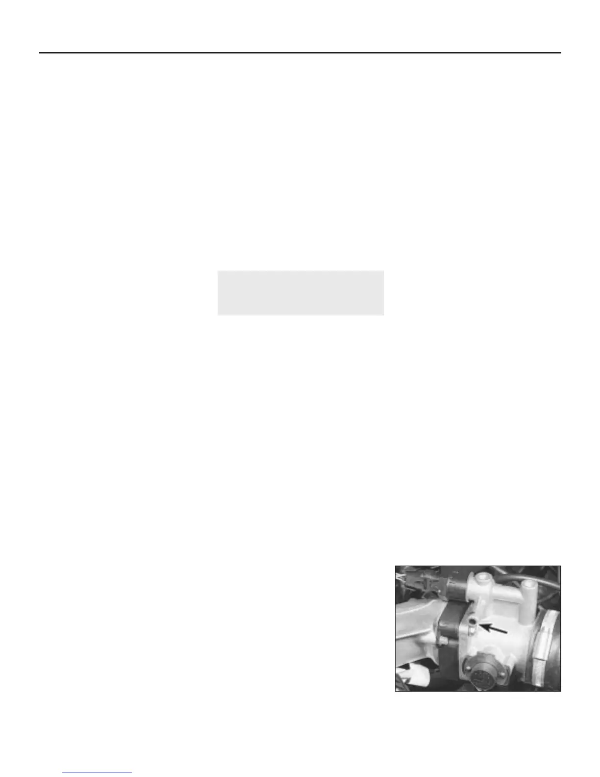
in the Specifications, hook out the tamperproof
plug over the idle mixture adjustment screw,
and turn the screw clockwise to enrich the
mixture, or anti-clockwise to weaken it as
necessary (see illustration).
4B•4 Fuel and exhaust systems - Lucas multi-point injection engines
11.12 Idle mixture adjustment screw
tamperproof plug (arrowed)
1380 Rover 800 Series Remake


 To Next Page
 Loading...
