13 With the CO content correctly adjusted,
switch off the engine and connect a
tachometer according to the manufacturer’s
instructions.
14 Before adjusting the base idle speed, the
stepper motor must be cycled to its fully-
extended position, using the following
procedure:
(a) Switch on the ignition.
(b) Disconnect the stepper motor wiring
multiplug on the top of the throttle
housing (see illustration).
(c) Switch off the ignition, wait five seconds,
and reconnect the stepper motor
multiplug.
(d) Switch on the ignition, wait five seconds,
and disconnect the stepper motor
multiplug again.
(e) Switch off the ignition, wait five seconds,
and reconnect the stepper motor
multiplug.
(f) Switch on the ignition, wait five seconds,
and disconnect the stepper motor
multiplug once more. The stepper motor
is now fully extended.
15 Start the engine, and allow it to idle until
normal operating temperature is again
reached.
16 Check the reading on the tachometer, and
compare this with the base idle speed figure
given in the Specifications.
17 If adjustment is necessary, hook out the
tamperproof plug over the idle speed
adjusting screw, and turn the adjusting screw
as necessary to achieve the correct setting
(see illustration).
18 Increase the engine speed to 2000 rpm
for ten seconds, then return it to idle.
19 Recheck the exhaust CO content, as
described earlier in this Section.
20 Switch off the ignition, and pull back the
dust cover over the throttle potentiometer
wiring multiplug.
21 Insert the probes from the voltmeter into
the back of the multiplug so that the voltmeter
black lead is connected to the pink/black
wire, and the red lead is connected to the light
green/pink wire.
22 Select millivolts on the voltmeter, then
switch on the ignition.
23 Check that the reading on the voltmeter
scale is now equal to the throttle potentiometer
voltage, as given in the Specifications. If this is
not the case, slacken the two retaining screws,
and slowly move the potentiometer body until
the correct reading is obtained (see
illustration). Tighten the screws securely.
24 Open and close the throttle several times,
then with it closed, check the voltmeter
reading once more. Repeat the adjustment if
the reading is now outside the specified
tolerance.
25 With the adjustments complete, switch off
the engine and disconnect the test instruments.
12 Fuel injection system
components -
removal and refitting
3
Note: Refer to the precautions contained in
Section 1 before proceeding.
Airflow meter - normally-
aspirated engines
Removal
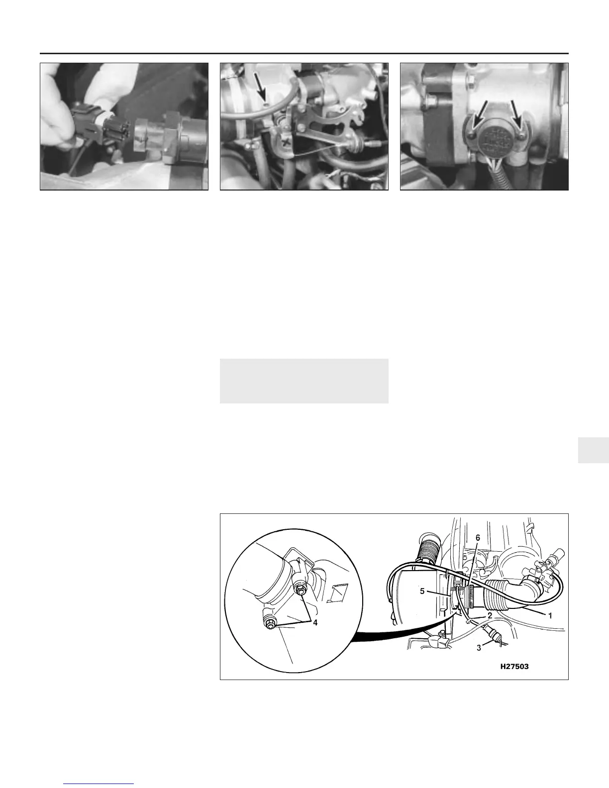
1 Slacken the hose clip and detach the air
trunking from the airflow meter (see
illustration).
2 Release the airflow meter wiring harness
from its retaining clip, and disconnect the
wiring multiplug.
3 Undo the two bolts securing the unit to its
mounting bracket, withdraw the unit from the
air cleaner body, and recover the seal.
Refitting
4 Refitting is a reversal of removal.
Airflow meter - turbocharged
engines
Removal
5 Remove the air cleaner and airflow meter
assembly as described in Section 2.
6 Slacken the clip and disconnect the
turbocharger intake hose from the airflow
meter.
7 Undo the four bolts and three nuts and
separate the airflow meter from the air cleaner
and bracket assembly.
Refitting
8 Refitting is a reversal of removal.
Idle speed stepper motor
Removal
9 Slide back the rubber dust cover (where
fitted), and disconnect the stepper motor
wiring multiplug.
Fuel and exhaust systems - Lucas multi-point injection engines 4B•5
11.23 Throttle potentiometer retaining
screws (arrowed)
11.17 Base idle speed adjusting screw
tamperproof plug (arrowed)
11.14 Disconnect the stepper motor wiring
multiplug
12.1 Airflow meter attachments
1 Air trunking
2 Wiring harness retaining
clip
3 Wiring multiplug
4 Retaining bolts
5 Airflow meter
6 Seal location
4B
1380 Rover 800 Series Remake


 To Next Page
 Loading...
