11 Keeping the cable in this position, screw
the square nut along the threaded portion of
the outer cable until it just touches the
support bracket.
12 Without moving the square nut, clip it into
its slot in the support bracket.
Models from VIN 152206
13 Switch the ignition on, wait five seconds
then switch it off again. This will move the
stepper motor to the adjustment position.
14 Refit the cable at the pedal end using a
reversal of removal.
15 At the throttle housing end, screw the
square adjusting nut fully onto the threaded
portion of the outer cable.
16 Connect the inner cable to the throttle
lever, and locate the outer cable in the slot in
the support bracket.
17 Hold the throttle lever closed and check
that the throttle position screw is in contact
with the stepper motor pin.
18 Pull the outer cable away from the throttle
lever until all slack and lost motion are taken
up.
19 Keeping the cable in this position, screw
the square nut along the threaded portion of
the outer cable until it just touches the
support bracket.
20 Without moving the square nut, clip it into
its slot in the support bracket.
4 Accelerator pedal -
removal and refitting
Refer to Part A, Section 4, but note that the
accelerator pedal switch is only fitted to
certain models.
5 Fuel system -
depressurisation
Note: Refer to the precautions contained in
Section 1 before proceeding.
Refer to Part B, Section 5.
6 Fuel pump -
removal and refitting
Note: Refer to the precautions contained in
Section 1 before proceeding.
Refer to Part A, Section 6.
7 Fuel gauge sender unit -
removal and refitting
Note: Refer to the precautions contained in
Section 1 before proceeding.
Refer to Part A, Section 7.
8 Fuel tank - removal,
inspection and refitting
Note: Refer to the precautions contained in
Section 1 before proceeding.
Refer to Part A, Section 8.
9 Unleaded petrol - general
information and usage
Refer to Part A, Section 9.
10 Fuel injection system -
general information
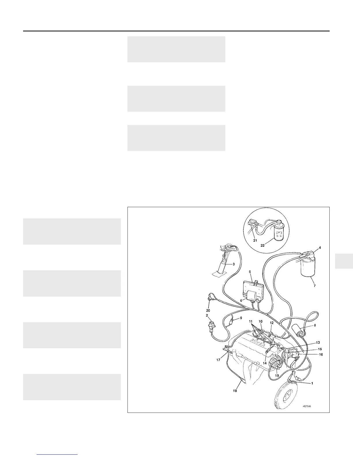
The Modular Engine Management System
(MEMS) is used on later models equipped
with the “T” series 4-cylinder engine. It
controls a multi-point fuel injection system, an
emissions control system and a programmed
ignition system as a total engine management
package (see illustration).
One Electronic Control Unit (ECU) controls
all the fuelling, emission and ignition
requirements of the engine. The ECU
incorporates short circuit protection and can
also store information on certain intermittent
faults for interrogation by computerised test
equipment.
the ECU utilises a speed/density method of
airflow measurement to calculate fuel delivery.
This method, using the engine as a pre-
calibrated vacuum pump, with its
characteristics stored in the ECU, measures
the air inlet temperature and inlet manifold
pressure, allowing the correct amount of fuel
per air density/speed to be injected.
Should certain elements of the system fail,
the ECU can implement a back-up facility,
allowing the system to operate at a reduced
level of performance until the fault can be
rectified.
A diagnostic socket allows tuning or fault
diagnosis to be carried out on test equipment
without disconnecting the ECU wiring
harness.
On early versions of the system, an
accelerator pedal switch triggers the ECU
between the main fuelling map when the
switch is open (accelerator pedal depressed)
and idle speed control when the switch is
closed (pedal released). The pedal switch also
Fuel and exhaust systems - MEMS multi-point injection engines 4C•3
10.1 Main components of the MEMS multi-point fuel injection system
4C
1380 Rover 800 Series Remake
1 Crankshaft sensor
2 Inertia switch
3 Fuel pump
4 Purge control valve
5 ECU
6 Relay module
7 Charcoal canister
8 Ignition coil
9 Diagnostic connector
10 Fuel pressure regulator
11 Fuel injectors
12 Fuel temperature sensor
13 Intake air temperature
sensor
14 Knock sensor
15 Throttle potentiometer
16 Stepper motor
17 Coolant temperature
sensor
18 Oxygen sensor
19 Distributor cap
20 Accelerator pedal switch
21 Purge control valve
22 Charcoal canister


 To Next Page
 Loading...
