controls an over-run fuel cut-off function. On
later versions of the system, the manifold
absolute pressure sensor is used to perform
the functions of the pedal switch.
The ECU, in determining optimum ignition
timing, receives information from the
crankshaft sensor (engine speed and
crankshaft position), manifold absolute
pressure sensor (engine load), knock sensor
(detonation), coolant temperature sensor
(engine temperature) and where fitted, from
the accelerator pedal switch (pedal position),
to determine main fuelling or idle speed
control.
It can be seen that the system is similar to
the earlier fuel injection system described in
Part B of this Chapter, the main differences
being the method of determining airflow (there
is no airflow meter) and the combining of the
fuel and ignition ECUs into one unit.
11 Fuel injection system -
testing and adjustment
5
Testing
1 If a fault appears in the fuel injection
system, first ensure that all the system wiring
connectors are securely connected and free
of corrosion. Then ensure that the fault is not
due to poor maintenance; ie, check that the
air cleaner filter element is clean, the spark
plugs are in good condition and correctly
gapped, the cylinder compression pressures
are correct, and that the engine breather
hoses are clear and undamaged, referring to
the relevant Sections of this Chapter, and to
Chapters 1 and 2 for further information.
2 If these checks fail to reveal the cause of
the problem, the vehicle should be taken to a
suitably equipped Rover dealer for testing on
Rover dedicated test equipment. This
equipment will locate the fault quickly and
simply, alleviating the need to test all the
system components individually, which is a
time-consuming operation that carries an
element of risk of damaging the ECU.
Adjustment
3 As all the fuelling and ignition requirements
are performed entirely by the electronic
control unit, no adjustments to the system are
possible. Any irregularities in idling speed
stability or engine performance may indicate a
fault in the system and should be referred to a
dealer for diagnosis and rectification.
12 Fuel injection system
components -
removal and refitting
3
Note: Refer to the precautions contained in
Section 1 before proceeding.
Intake air temperature sensor
Removal
1 Disconnect the wiring multiplug from the
temperature sensor located on the inlet
manifold.
2 Unscrew the sensor and remove it from the
manifold.
Refitting
3 Refitting is a reversal of removal.
Throttle housing
Removal
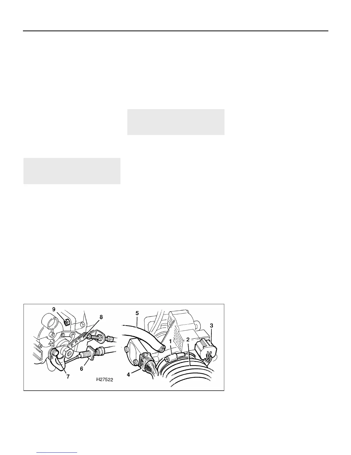
4 Disconnect the wiring multiplugs from the
stepper motor and throttle potentiometer (see
illustration).
5 Slacken the clip and detach the air intake
hose from the throttle housing.
6 Disconnect the accelerator cable from the
throttle lever and support bracket as
described in Section 3.
7 On automatic transmission models,
disconnect the kick-down cable from the
throttle lever and support bracket referring to
Chapter 7, Part B if necessary.
8 Release the clips and disconnect the
breather hoses.
9 Unscrew the four nuts securing the throttle
housing to the inlet manifold and remove the
throttle housing.
Refitting
10 Refitting is a reversal of removal.
Reconnect and adjust the accelerator cable
as described in Section 3, and on automatic
transmission models, the kick-down cable as
described in Chapter 7, Part B.
Throttle potentiometer
Note: If the potentiometer is being renewed, it
will be necessary to have the new unit
adjusted by a Rover dealer on completion.
Removal
11 Remove the throttle housing as described
previously.
12 Using a dab of paint, mark the position of
the potentiometer in relation to the throttle
housing, so that if the original unit is refitted,
its position can be restored.
13 Undo the two screws, remove the unit
from the throttle housing, and recover the
gasket.
Refitting
14 Refit the potentiometer and gasket, align
the previously-made mark, then tighten the
two retaining screws.
15 If a new unit is being fitted, position it
centrally within its adjustment range.
16 Refit the throttle housing as described
previously.
17 Have the potentiometer adjusted by a
Rover dealer if a new unit was fitted.
Accelerator pedal switch
18 Refer to Part A, Section 4.
Fuel temperature sensor
Removal
19 Disconnect the wiring multiplug from the
temperature sensor located on the fuel rail.
20 Unscrew the sensor, remove it from the
fuel rail and recover the sealing washer.
Refitting
21 Refitting is a reversal of removal, but use a
new sealing washer.
Fuel pressure regulator
Removal
22 Disconnect the battery negative (earth)
lead (refer to Chapter 5, Section 1).
23 Relieve the fuel system pressure as
described in Part B, Section 5.
24 Disconnect the vacuum hose from the top
of the regulator (see illustration).
25 Release the clip and disconnect the fuel
return hose from the base of the regulator.
26 Undo the regulator bracket retaining
bolts, withdraw the regulator from the fuel rail
and recover the O-ring seal. Plug the fuel rail
while the regulator is removed.
4C•4 Fuel and exhaust systems - MEMS multi-point injection engines
12.4 Stepper motor and throttle potentiometer details
1 Intake hose clip
2 Intake hose
3 Stepper motor multiplug
4 Potentiometer multiplug
5 Breather hose
6 Throttle cable bracket
7 Cam lever
8 Kick-down cable cam lever
9 Throttle housing nuts
1380 Rover 800 Series Remake


 To Next Page
 Loading...
