Refitting
27 Refitting is a reversal of removal, but use a
new O-ring seal.
Plenum chamber
Removal
28 Disconnect the battery negative (earth)
lead (refer to Chapter 5, Section 1).
29 Slacken the hose clip and detach the air
intake trunking from the throttle housing.
30 Undo the four nuts securing the throttle
housing to the plenum chamber, ease the
housing off the studs, and move it slightly to
one side.
31 Disconnect the vacuum hoses at each
end of the plenum chamber.
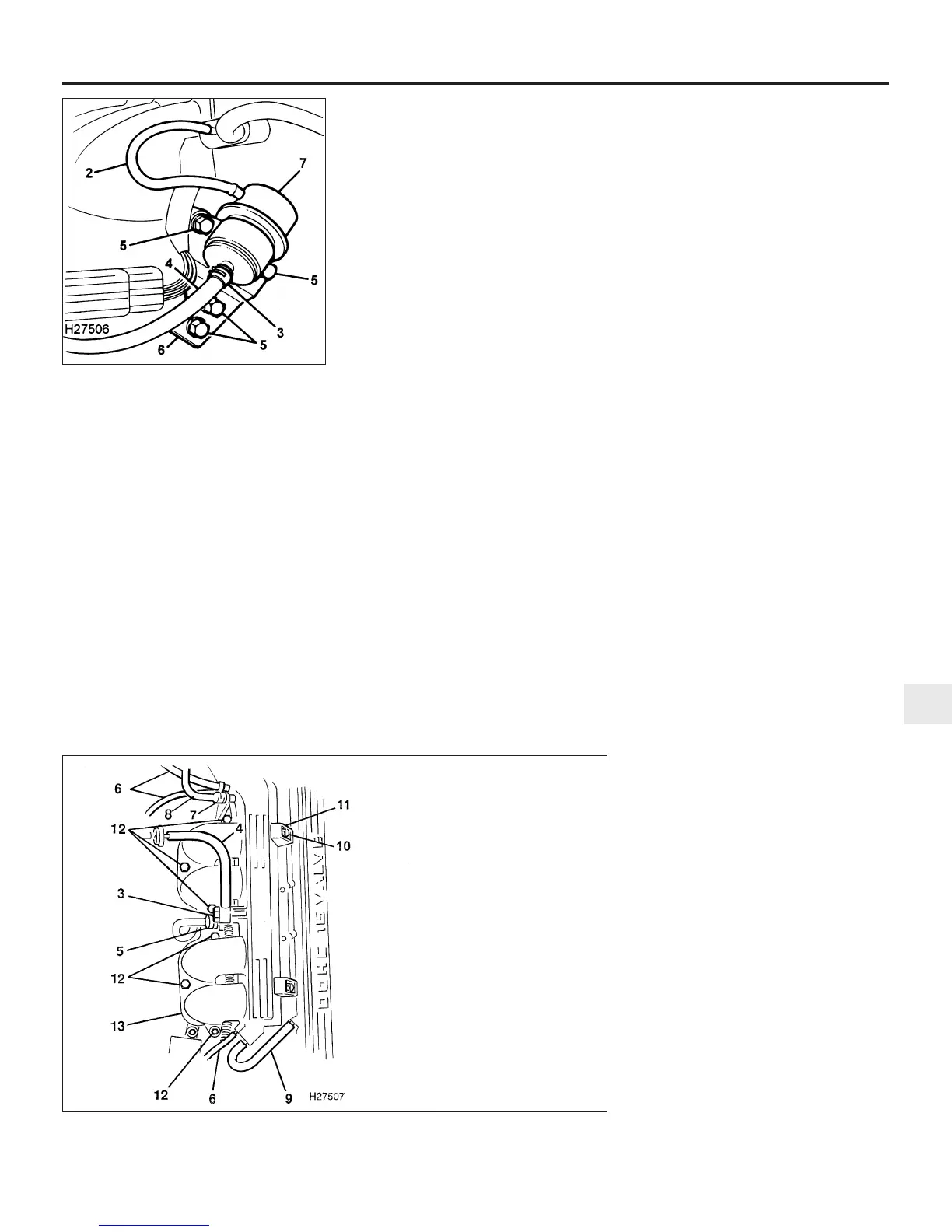
32 Disconnect the purge control valve hose
from the plenum chamber (see illustration).
33 Unscrew the brake servo vacuum hose
banjo union bolt and recover the two copper
washers from the banjo union.
34 Detach the engine breather hose from the
plenum chamber.
35 Disconnect the fuel temperature sensor
wiring multiplug.
38 Undo the two bolts securing the plenum
chamber mounting brackets to the camshaft
cover.
39 Undo the six bolts securing the rear of the
plenum chamber to the inlet manifold.
40 Lift the plenum chamber off the manifold,
and recover the gasket.
41 Clean the manifold and plenum chamber
mating faces and obtain a new gasket.
Refitting
42 Refitting is a reversal of removal. Use a
new gasket and tighten the nuts and bolts to
the specified torque.
Fuel injectors and fuel rail
Removal
43 Disconnect the battery negative (earth)
lead (refer to Chapter 5, Section 1).
44 Relieve the fuel system pressure as
described in Part B, Section 5.
45 Remove the plenum chamber as
described previously.
46 Undo the four bolts and disconnect the
fuel feed hose flange bracket from the side of
the fuel rail. Plug the hose and fuel rail after
disconnection.
47 Disconnect the multiplugs from each of
the four injectors and move the injector wiring
harness aside.
48 Disconnect the vacuum hose from the top
of the fuel pressure regulator.
49 Release the clip and disconnect the fuel
return hose from the base of the regulator.
50 Undo the regulator bracket retaining
bolts, withdraw the regulator from the fuel rail
and recover the O-ring seal. Plug the fuel rail
while the regulator is removed.
51 Undo the three bolts securing the fuel rail
to the inlet manifold.
52 Ease the four injectors out of their inlet
manifold locations, and lift up the injector and
fuel rail assembly. Recover the O-ring seal
from each injector outlet.
53 Extract the retaining clips, and remove the
injectors from the fuel rail. Recover the O-ring
seal from each injector inlet.
Refitting
54 Refitting is a reversal of removal, but
renew the injector inlet and outlet O-rings.
Electronic control unit and relay
module
Removal
55 Lift the charcoal canister out of its
mounting bracket and move it to one side.
56 Release the relay module from the bracket
on the front of the ECU.
57 Disconnect the two wiring multiplugs and
the vacuum hose, then undo the three bolts
and remove the ECU from the mounting
bracket.
Refitting
58 Refitting is a reversal of removal.
Inertia switch
Removal
59 Disconnect the wiring multiplug, undo the
two screws and remove the switch from the
engine compartment bulkhead.
Refitting
60 Refitting is a reversal of removal.
Boost control solenoid
(Turbocharged engines)
Removal
61 Refer to Chapter 5, and remove the
battery.
62 Slacken the clip and release the air intake
hose on the side of the air cleaner body.
63 Slacken the clip and release the boost
control solenoid valve hose from its
connection next to the air intake hose on the
air cleaner.
64 Undo the two bolts on the side of the air
cleaner body and remove the unit from the
engine compartment.
65 Release the clips and disconnect the
three hoses from the boost control solenoid.
66 Disconnect the wiring multiplug, undo the
retaining bolt and remove the solenoid from
the battery tray.
Refitting
67 Refitting is a reversal of removal.
Camshaft sensor (Turbocharged
engines)
Removal
68 Disconnect the sensor wiring harness at
the connector.
Fuel and exhaust systems - MEMS multi-point injection engines 4C•5
12.24 Fuel pressure regulator attachments
2 Vacuum hose
3 Fuel return hose clip
4 Fuel return hose
5 Regulator bracket retaining bolts
6 Regulator bracket
7 Fuel pressure regulator
12.32 Plenum chamber attachment details
4C
1380 Rover 800 Series Remake
3 Brake servo banjo bolt
4 Brake servo vacuum
pipe
5 Fuel temperature sensor
multiplug
6 Vacuum hoses
7 Purge control valve hose
8 Breather hose
10 Mounting bracket bolts
11 Mounting brackets
12 Plenum chamber to inlet
manifold bolts
13 Plenum chamber


 To Next Page
 Loading...
