1 General information and
precautions
The fuel system used on V6 engine Rover
models consists of a centrally-mounted fuel
tank, electric fuel pump and Honda PGM-Fi
programmed fuel injection system A more
detailed description of the system is
contained in Section 10.
The exhaust system consists of a front,
intermediate and rear section, suspended
from the underbody on rubber mountings, and
bolted to two cast iron manifolds at the front.
A catalytic converter is fitted between the
front and intermediate sections on later
models and a flexible joint is also incorporated
in the front section, to allow for engine and
exhaust system movement.
Precautions
Warning: Many of the
procedures in this Chapter
require the removal of fuel lines
and connections, which may
result in some fuel spillage. Petrol is
extremely flammable, so take extra
precautions when you work on any part of
the fuel system. Don’t smoke, or allow
open flames or bare light bulbs, near the
work area. Don’t work in a garage where a
natural gas-type appliance (such as a
water heater or clothes dryer) with a pilot
light is present. If you spill any fuel on your
skin, rinse it off immediately with soap and
water. When you perform any kind of work
on the fuel system, wear safety glasses,
and have a Class B type fire extinguisher
on hand. Before carrying out any operation
on the fuel system, refer also to the
precautions given in “Safety first!” at the
beginning of this manual, and follow them
implicitly. Petrol is a highly-dangerous and
volatile liquid, and the precautions
necessary when handling it cannot be
overstressed.
Reference must also be made to Chapter 5,
Section 1 for precautionary notes concerning
the ignition system and battery disconnection,
and to any further safety-related text
contained within the appropriate Section,
before working on the vehicle.
Certain adjustment points in the fuel system
are protected by tamperproof caps, plugs or
seals. In some territories, it is an offence to
drive a vehicle with broken or missing
tamperproof seals. Before disturbing a
tamperproof seal, first check that no local or
national laws will be broken by doing so, and
fit a new tamperproof seal after adjustment is
complete, where required by law. Do not
break tamperproof seals on any vehicle whilst
it is still under warranty.
When working on fuel system components,
scrupulous cleanliness must be observed and
care must be taken not to introduce any
foreign matter into the fuel lines or
components.
2 Air cleaner assembly and
intake components -
removal and refitting
1
Note: Air cleaner element renewal is
described in Chapter 1.
Note: Due to the limited space available,
access to the air intake trunking and air
cleaner assembly can be improved if the
battery is removed first. If this is to be done,
refer to Chapter 5, Section 1, for precautions
concerning battery disconnection.
Air intake trunking
Removal
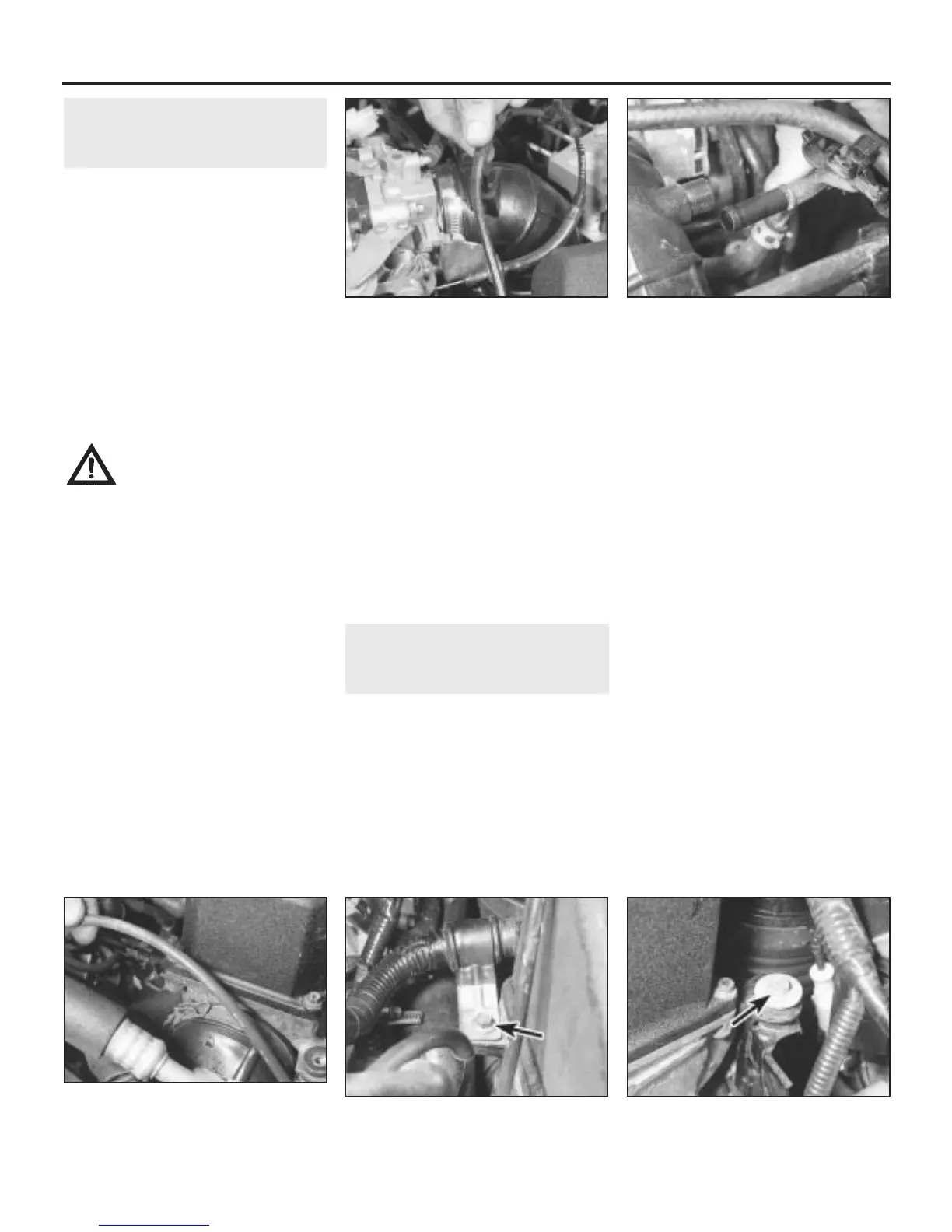
1 Release the coil HT cable from the clip on
top of the upper intake trunking (see
illustration).
2 Undo the breather pipe support bracket
bolt and remove the breather pipe from the
side of the upper intake trunking (see
illustration).
3 Slacken the clip securing the upper
trunking to the throttle body and the clip
securing the lower intake trunking to the air
cleaner assembly.
4 Release the trunking from the throttle body
and air cleaner; slacken the centre clip,
securing the upper and lower trunking parts
together.
5 Separate the upper trunking from the lower
trunking and manipulate both parts out of the
engine compartment.
Refitting
6 Refitting is a reversal of removal.
Air cleaner assembly
Removal
7 Remove the air intake trunking as described
previously.
8 Release the clip securing the resonator
vacuum hose to the front of the air cleaner
assembly and undo the wiring harness
support clip bolt at the rear (see
illustrations).
9 Slacken the air duct retaining clip.
10 Undo the two bolts securing the air
cleaner assembly to the battery tray (see
illustrations).
4D•2 Fuel and exhaust systems - Honda PGM-Fi injection engines
2.10a Undo the rear bolt arrowed . . .2.8b . . . and undo the wiring harness
support clip bolt (arrowed) at the rear
2.8a Release the clip securing the
resonator vacuum hose to the front of the
air cleaner assembly . . .
2.2 Remove the breather pipe from the
side of the upper intake trunking
2.1 Release the coil HT cable from the clip
on top of the upper intake trunking
1380 Rover 800 Series Remake


 To Next Page
 Loading...
