8 Fuel tank - removal,
inspection and refitting
Refer to Part A, Section 8.
9 Unleaded petrol - general
information and usage
Note: The information given in this Chapter is
correct at the time of writing, and applies only
to petrols currently available in the UK. If
updated information is thought to be required,
check with a Rover dealer. If travelling abroad,
consult one of the motoring organisations (or a
similar authority) for advice on the petrols
available and their suitability for your vehicle.
1 The recommended fuel is given in the
Specifications at the beginning of this
Chapter, followed by the equivalent petrol on
sale in the UK.
2 RON and MON are different testing
standards; RON stands for Research Octane
Number (also written as RM), while MON
stands for Motor Octane Number (also written
as MN).
3 All non-catalyst equipped V6 engine
models covered by this manual are designed
to run on leaded or unleaded petrols.
Depending on the petrol used, the ignition
timing will have to be adjusted accordingly.
Details of this procedure are covered in
Chapter 5, Section 10. Only unleaded petrol
may be used in those models fitted with a
catalytic converter.
10 Fuel injection system -
general information
The Honda PGM-Fi programmed fuel
injection system is used on all V6 engine
models covered by this manual. There are
detail differences between the system used
on the 2.5 litre engines and that used on
2.7 litre models, but these are of a minor
nature and mainly reflect the system’s
development over the years. The system is a
complex and highly sophisticated total engine
management package, controlling the fuel
injection, the fuel and exhaust emissions, and
the ignition system, from one electronic
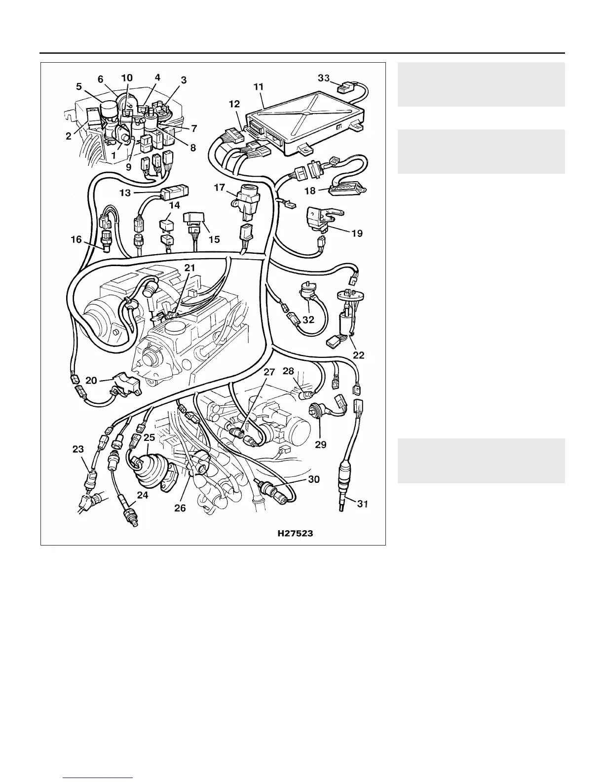
control unit (ECU) (see illustration).
The tank-mounted fuel pump supplies fuel
under pressure to the fuel rails; the pressure
being controlled by the fuel pressure
regulator. Fuel from the fuel rails is supplied to
the fuel injectors which are then operated by
the ECU according to a number of operating
parameters.
The ECU contains memories for the basic
fuel injector opening times for various engine
speed and load conditions. Numerous
sensors on and around the engine are used to
4D•4 Fuel and exhaust systems - Honda PGM-Fi injection engines
10.1 Main components of the PGM-Fi programmed fuel injection system
Note: Components and locations may differ slightly between models
1 Ignition timing sensor
2 Manifold absolute pressure
sensor
3 Constant vacuum control
valve
4 Air suction control solenoid
valve
5 EGR control solenoid valve
6 Throttle dashpot air filter
7 Air reservoir
8 Pressure regulator control
cut-off solenoid valve
9 Bypass control solenoid
valve A
10 Bypass control solenoid
valve B
11 Main system ECU
12 Cooling fan timer module
13 Injector resistor pack
14 Air conditioning clutch
relay
15 Main system relay
16 Oil temperature sensor
17 Inertia switch
18 Transmission shift position
switch
19 Absolute pressure sensor
20 Crank/cylinder sensor
21 Fuel injectors
22 Fuel pump
23 Power steering switch
24 Oxygen sensor
25 EGR valve lift sensor
26 TDC sensor
27 Intake air temperature
sensor
28 Electronic idle control valve
29 Throttle angle sensor
30 Coolant temperature
sensor
31 Speedometer transducer
32 Resonator control valve
solenoid
33 ECU link connector
1380 Rover 800 Series Remake


 To Next Page
 Loading...
