14 Locate the adjuster and hook out the
tamperproof cap over the adjusting screw, if
fitted.
15 Refer to the engine tuning procedure
information contained above before starting.
16 Switch off all electrical accessories, and
ensure that they remain switched off
throughout the adjustment procedure.
17 If, during the adjustment procedure, the
cooling fan operates, or if adjustment is not
completed within two minutes, accelerate the
engine to 2000 rpm, and hold this speed for
ten seconds. Repeat this every two minutes
until the adjustments are completed.
18 With the engine idling and the exhaust gas
analyser connected, take a reading of the
exhaust gas CO content. If this is not as given
in the Specifications, turn the screw clockwise
to enrich the mixture, or anti-clockwise to
weaken it as necessary.
19 On completion, disconnect the exhaust
gas analyser and check the idle speed setting
as described above.
12 Fuel injection system
components -
removal and refitting
3
Note: Refer to the precautions contained in
Section 1 before proceeding.
Atmospheric pressure sensor
Removal
1 Open the fusebox cover under the facia on
the driver’s side.
2 Undo the retaining screw and withdraw the
sensor from the mounting bracket.
3 Disconnect the wiring multiplug and
remove the sensor.
Refitting
4 Refitting is a reversal of removal.
Resonator
Removal
5 Apply the handbrake, jack up the front of
the car and support it on axle stands.
6 Undo the two screws and one bolt securing
the access panel to the underside of the front
wheelarch on the left-hand side.
7 Undo the four remaining screws, disengage
the access panel from the front spoiler, and
remove it from under the car.
8 Disconnect the wiring multiplug from the
control solenoid.
9 Disconnect the vacuum hose at the T-piece
connector.
10 Undo the two bolts and withdraw the
resonator assembly from under the front
wheelarch.
11 Remove the spacers and rubber
mountings from the resonator.
12 With the unit removed, the control
solenoid and valve control diaphragm,
together with the pipes and hoses, can be
removed as required.
Refitting
13 Refitting is a reversal of removal.
Throttle body
Removal
14 Partially drain the cooling system as
described in Chapter 1, to below the level of
the throttle body.
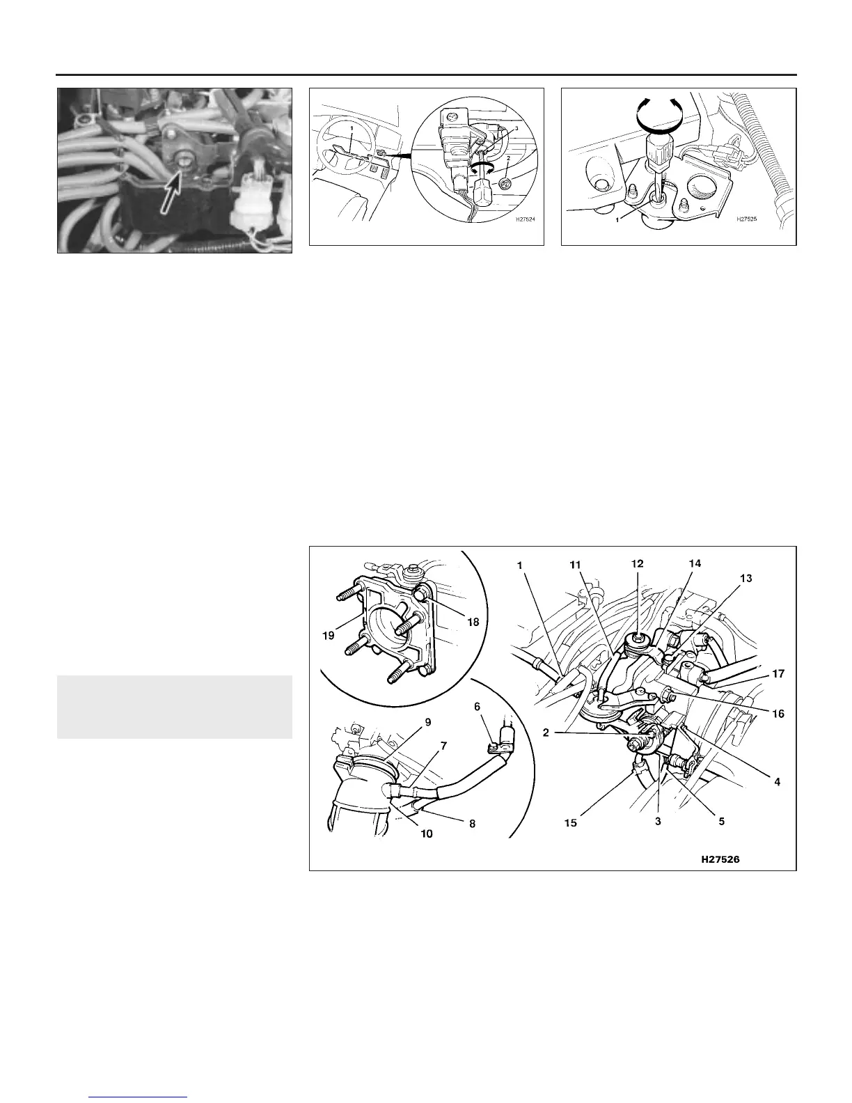
15 Open the throttle fully by hand, and slip
the accelerator inner cable end out of the slot
on the throttle lever (see illustration).
4D•6 Fuel and exhaust systems - Honda PGM-Fi injection engines
12.15 Throttle body components and attachment details
1 Outer accelerator cable
2 Inner accelerator
connection
3 Kick-down cable
4 Kickdown cable support
bracket screws
5 Throttle angle sensor
wiring multiplug
6 Breather pipe retaining bolt
7 Breather pipe upper
connection
8 Breather pipe lower
connection
9 Intake trunking clip
10 Intake trunking
11 Throttle diaphragm vacuum
hose
12 Support strap rear bolt
13 Support strap front bolt
14 Support strap
15 Lower air hose
16 Throttle body retaining nuts
17 Throttle body
18 Rubber insulator retaining
bolts
19 Rubber insulator
11.13c Idle mixture adjuster screw (1)
under the driver’s seat on later 2.7 litre
non-catalyst engines
11.13b Idle mixture adjuster location on
early 2.7 litre non-catalyst engines
1 Remove fusebox cover for access
2 Hook out tamperproof cap
3 Turn adjuster as required
11.13a This is actually the ignition timing
sensor/adjuster (arrowed) in the control
box on 2.7 litre engines, but on 2.5 litre
models, this is where you will find the idle
mixture adjuster
1380 Rover 800 Series Remake


 To Next Page
 Loading...
