16 Slacken the outer cable locknuts, then
withdraw the outer cable from the support
bracket.
17 On automatic transmission models,
release the kickdown cable inner cable end
from the throttle lever.
18 Undo the two screws securing the
kickdown cable support bracket to the throttle
body and move the bracket and cable to one
side.
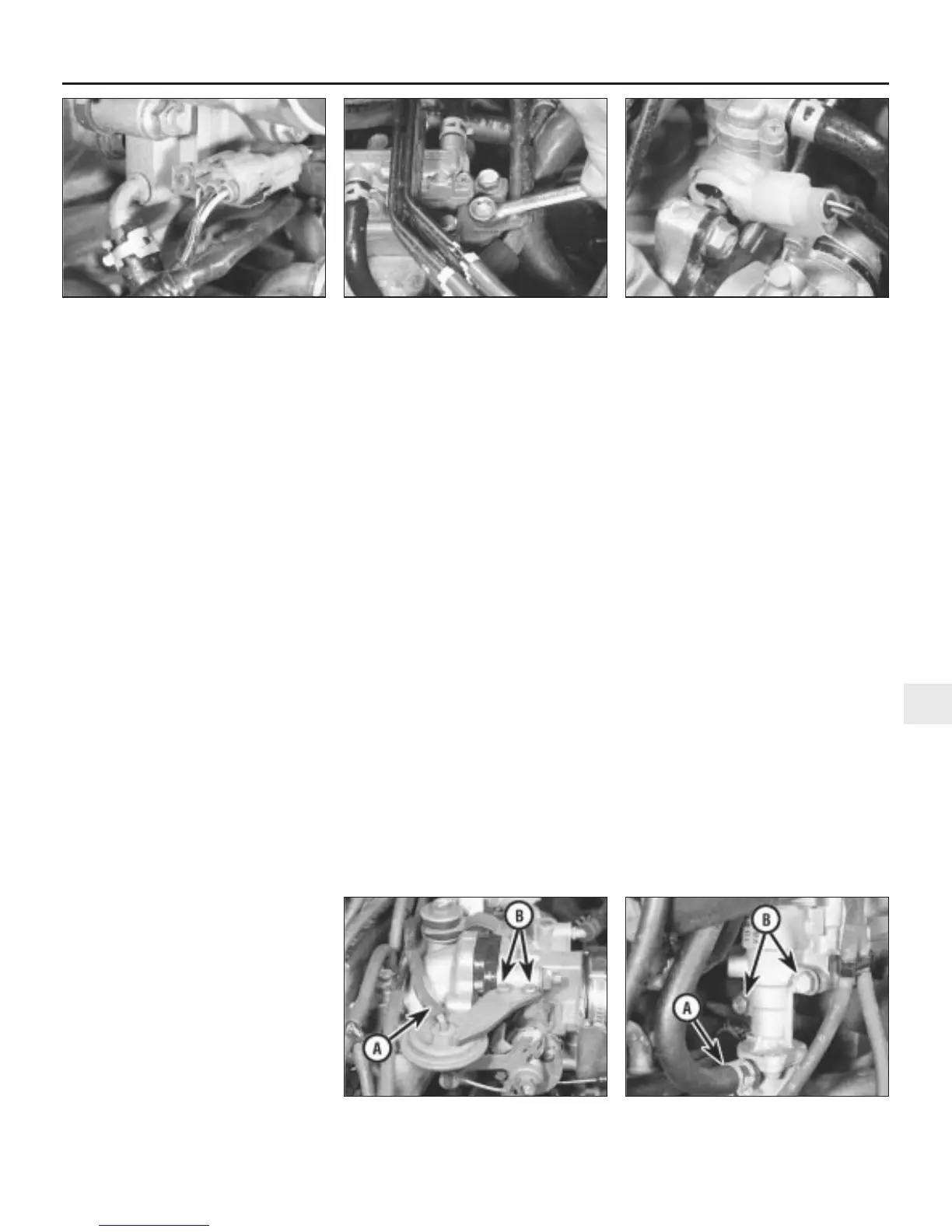
19 Disconnect the wiring multiplug from the
throttle angle sensor (see illustration).
20 Release the coil HT cable from the clip on
top of the air intake trunking.
21 Undo the breather pipe support bracket
bolt and remove the breather pipe from the
side of the intake trunking.
22 Slacken the clip and release the trunking
from the throttle body.
23 Disconnect the vacuum hose from the
throttle diaphragm.
24 Undo the two bolts and remove the
support strap from the top of the throttle
body.
25 Release the clip and disconnect the lower
air hose from the underside of the throttle
body.
26 Undo the four nuts, move the air intake
trunking aside, and withdraw the throttle body
from the studs of the rubber insulator.
27 If required, the rubber insulator can be
removed from the inlet manifold after undoing
the four retaining bolts.
Refitting
28 Refitting is a reversal of removal. Adjust the
accelerator cable as described in Section 3,
and refill the cooling system (Chapter 1).
Electronic idle control valve
Removal
29 Partially drain the cooling system as
described in Chapter 1, to below the level of
the idle control valve.
30 Undo the bolts securing the vacuum pipe
and crankcase ventilation pipe support
brackets (see illustration).
31 Disconnect the wiring multiplug from the
idle control valve (see illustration).
32 Release the clips and disconnect the two
coolant hoses from the idle control valve.
33 Undo the two bolts and remove the idle
control valve from the inlet manifold. Recover
the sealing O-ring from the base of the valve.
Refitting
34 Refitting is a reversal of removal but use a
new O-ring seal. Refill the cooling system
(Chapter 1), and adjust the idle speed (Sec-
tion 11).
Dashpot diaphragm assembly
Removal
35 Disconnect the vacuum hose from the top
of the diaphragm (see illustration).
36 Undo the two screws securing the
diaphragm bracket to the throttle body.
37 Disconnect the operating rod from the
throttle lever and remove the diaphragm
assembly.
Refitting
38 Refitting is a reversal of removal.
Fast idle valve
Removal
39 Partially drain the cooling system as
described in Chapter 1, to below the level of
the fast idle valve.
40 Release the clips and disconnect the two
coolant hoses from the fast idle valve (see
illustration).
41 Undo the three bolts and remove the
valve from the inlet manifold. Recover the two
O-ring seals.
Refitting
42 Refitting is a reversal of removal, but
renew the O-ring seals and refill the cooling
system, as described in Chapter, 1 on
completion.
Front fuel rail and injectors
Removal
43 Disconnect the battery negative (earth)
lead (refer to Chapter 5, Section 1).
44 Relieve the fuel system pressure as
described in Section 5.
45 Disconnect the spark plug HT leads from
the three rear spark plugs, and identify the
leads for correct reconnection.
46 Release the HT leads from the support
clips and from the top of the inlet manifold
cover and move the leads clear (see
illustration).
47 Undo the bolt securing the fuel pipe clip at
the corner of the inlet manifold cover.
48 Release the clips and disconnect the
breather hose from the inlet manifold cover
and camshaft cover.
49 Open the throttle fully by hand, and slip
the accelerator inner cable end out of the slot
on the throttle lever.
50 Slacken the outer cable locknuts;
withdraw the outer cable from the support
bracket. Release the cable from the clips and
move it clear.
Fuel and exhaust systems - Honda PGM-Fi injection engines 4D•7
12.31 Disconnect the wiring multiplug
from the idle control valve
12.30 Undo the bolts securing the vacuum
pipe and crankcase ventilation pipe
support brackets
12.19 Throttle angle sensor wiring
multiplug location
12.40 Fast idle valve coolant hose (A) and
mounting bolts (B)
12.35 Dashpot diaphragm vacuum
hose (A) and retaining screws (B)
4D
1380 Rover 800 Series Remake


 To Next Page
 Loading...
