Refitting
76 Refitting is a reversal of removal but use a
new sealing O-ring.
Electronic control unit
Removal
77 Disconnect the battery negative (earth)
lead (refer to Chapter 5, Section 1).
78 Remove the driver’s seat as described in
Chapter 11.
79 Undo the four bolts securing the ECU to
the floor. Lift off the ECU cover and collect the
spacers between the ECU flange and the
floor.
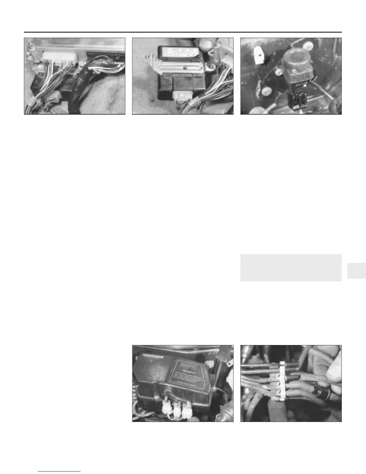
80 Disconnect the ECU wiring multiplugs
(see illustration).
81 Where fitted, undo the two bolts and
remove the cooling fan timer module from
the ECU base (see illustration). Remove the
ECU.
Refitting
82 Refitting is a reversal of removal.
Inertia switch
Removal
83 On early models the switch is located
behind the centre console inside the car.
84 Remove the stud from the centre console
side cover on the left-hand side, and remove
the cover.
85 Undo the two screws securing the inertia
switch to the mounting plate, disconnect the
wiring multiplug and remove the switch.
86 Check the operation of the switch by
striking the forward-facing side hard against
the palm of your hand. The setting button
should trip out when this is done. If not, renew
the switch.
87 On later models, disconnect the wiring
multiplug, undo the two screws and remove
the switch from the engine compartment
bulkhead (see illustration).
Refitting
88 Refitting is a reversal of removal. Press
the button down to reset the switch after
installation.
Main control box
89 In addition to the sensors, valves and
solenoids described previously in this Section,
a number of additional units are located in the
main control box mounted on the engine
compartment bulkhead. These devices are
used by the ECU for control of the fuel,
ignition and emissions control systems. Many
of the sensors utilise manifold vacuum for
their operation and are connected by means
of a series of numbered vacuum hoses and
pipes to various locations on, and around, the
engine. Three wiring multiplugs connect the
sensors electrically to the main harness.
90 The layout, and number of sensors fitted,
varies considerably according to engine,
model year, emission equipment level, and
vehicle accessories or options. Each of the
sensors can be renewed separately, but
testing, either individually, or as part of their
respective system, must be entrusted to a
dealer with dedicated test equipment.
Removal
91 Disconnect the battery negative (earth)
lead (refer to Chapter 5, Section 1).
92 Slacken the two bolts securing the control
box to the bulkhead.
93 Undo the three screws and lift off the
control box upper cover (see illustration).
94 Note the connections, then release the
wiring multiplugs from the mounting brackets
on the front of the control box and disconnect
them.
95 Remove the control box lower cover from
the valve plate assembly.
96 Check that each of the vacuum hoses and
its corresponding pipe on the pipe block is
numbered. If not, label each hose and pipe.
97 Some of the sensors are accessible at this
stage and if they are to be renewed
individually, disconnect the vacuum hose,
undo the screws and remove the relevant unit.
If the complete control box is being removed,
proceed as follows.
98 Pull the vacuum hoses off the pipe stubs
(see illustration).
99 Undo the bolts securing the valve plate
mounting brackets and remove the assembly
from the bulkhead.
100 Any sensors not previously accessible
can now be removed from the valve plate.
Refitting
101 Refitting is a reversal of removal, but
ensure that the labelled vacuum hoses are
connected to the correct pipe stub.
13 Cruise control system -
general information
A cruise control system is available as
standard or optional equipment on certain
V6 engine models. The system uses electro-
mechanical devices to accurately maintain the
vehicle road speed without the use of the
accelerator pedal.
The system is controlled by an electronic
control unit (ECU) which responds to inputs
from the master and set/resume switches, the
Fuel and exhaust systems - Honda PGM-Fi injection engines 4D•9
12.87 Inertia switch location on the engine
compartment bulkhead
12.81 Where fitted, undo the two bolts and
remove the cooling fan timer module
12.80 Disconnect the ECU wiring
multiplugs
12.98 Pull the vacuum hoses off the pipe
stubs
12.93 Undo the three screws and lift off
the control box upper cover
4D
1380 Rover 800 Series Remake


 To Next Page
 Loading...
