vehicle speed sensor, the clutch and brake
pedal switches and the shift control switch on
the transmission. When the system is
engaged, the ECU sends signals to the cruise
control actuator which regulates the
accelerator pedal position by means of a
stepper motor and connecting cable. Once
the driver has initiated the system, the road
speed will be constantly monitored and
maintained by the cruise control actuator.
The system can be disengaged at any time
either by use of the control switches or by
depressing the brake (and where applicable
the clutch) pedals, or moving the automatic
transmission gear selector to neutral. The
ECU memory stores the previously set road
speed which can be re-engaged by use of the
resume switch.
14 Cruise control system
components -
removal and refitting
3
Cruise control actuator
Removal
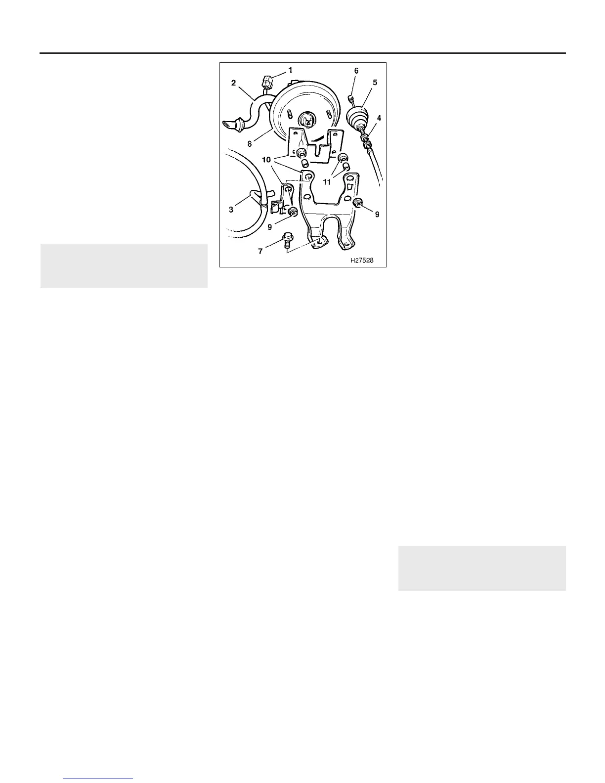
1 Disconnect the wiring multiplug from the
actuator stepper motor (see illustration).
2 Disconnect the vacuum and vent hoses
from the actuator.
3 Slacken the locknuts on the operating cable
at the support bracket on the actuator.
4 Release the rubber boot and disconnect the
inner cable from the actuator rod.
5 Undo the two mounting bolts securing the
actuator bracket to the body; remove the
actuator and bracket from the engine
compartment.
6 If necessary, the mounting brackets and
solenoid valves can now be removed from the
actuator.
Refitting
7 Refitting is a reversal of removal, but adjust
the operating cable as described in the
following sub-Section on completion.
Operating cable
Removal
8 Slacken the outer cable locknuts at the
support bracket on the cruise control
actuator.
9 Release the rubber boot and disconnect the
inner cable from the actuator rod.
10 From inside the car, release the
turnbuckles and lift out the trim panel over the
clutch, brake and accelerator pedals.
11 Disconnect the inner cable from the
accelerator pedal.
12 Release the cable from the engine
compartment bulkhead, and the support clips,
and withdraw the cable from the car.
Refitting and adjustment
13 Refit the cable using a reversal of removal
then adjust it as follows.
14 First check that the accelerator cable is
correctly adjusted as described in Section 3.
15 Start the engine and allow it to idle.
16 Release the rubber boot at the actuator
rod.
17 Push the actuator rod in, and measure the
movement until the engine speed just begins
to rise.
18 Adjust the position of the outer cable, by
means of the locknuts, so that there is 9.5 to
12.5 mm of actuator rod movement before the
engine speed increases off idle.
19 Tighten the locknuts and refit the rubber
boot on completion.
Cruise control switches
Main facia switch
20 The procedure for removal and refitting of
the main switch is described in Chapter 12,
Section 4.
Set/resume switch
21 Refer to Chapter 10, Section 18 and
remove the steering wheel pad or the airbag
module as applicable.
22 Disconnect the switch wiring multiplug
and the two Lucar connectors at the steering
wheel.
23 On early models, release the switch unit
from the steering wheel pad. On later models,
undo the two switch retaining screws and the
single mounting bracket-to-steering wheel
retaining bolt.
24 Remove the mounting bracket and
withdraw the switch from the steering wheel.
25 Refit the switch using a reversal of
removal then refit the steering wheel pad or
airbag module as described in Chapter 10.
Clutch and brake switches
26 To remove the clutch switch, release the
turnbuckles and lift out the trim panel over the
clutch, brake and accelerator pedals.
27 Disconnect the switch wiring multiplug.
28 Slacken the locknut and unscrew the
switch from the pedal bracket.
29 Refit the switch by screwing it in until the
plunger is fully depressed, then tighten the
locknut.
30 Reconnect the multiplug and refit trim
panels.
31 The brake switch is combined with the
stop-light switch and reference should be
made to Chapter 9, Section 21.
Electronic control unit
Removal
32 Release the turnbuckles and lift out the
trim panel over the clutch, brake and
accelerator pedals.
33 Disconnect the ECU multiplug, undo the
retaining bolt and withdraw the ECU from its
location on the door pillar bracket.
Refitting
34 Refitting is a reversal of removal.
15 Exhaust system - general
information and component
renewal
With the exception of the twin downpipes,
the exhaust system is the same as used on
4-cylinder engines. Refer to Part A, Section 13
for exhaust system details, and to Part E,
Section 3, for information on the catalytic
converter.
4D•10 Fuel and exhaust systems - Honda PGM-Fi injection engines
14.1 Cruise control actuator attachment
details
1 Stepper motor wiring multiplug
2 Vent hose
3 Vacuum hose
4 Outer operating cable locknuts
5 Rubber boot
6 Inner operating cable
7 Actuator bracket mounting bolts
8 Actuator
9 Actuator to bracket mounting nuts
10 Bracket components
11 Bushes and sleeves
1380 Rover 800 Series Remake


 To Next Page
 Loading...
