the exhaust system. On all models where a
catalytic converter is fitted, the system is of
the closed-loop type, in which an oxygen
sensor in the exhaust system provides the fuel
injection/ignition system ECU with constant
feedback on the oxygen content of the
exhaust gasses. This enables the ECU to
adjust the mixture by altering injector opening
time, to provide the best possible conditions
for the converter to operate.
11 The oxygen sensor has a built-in heating
element, controlled by the ECU to quickly
bring the sensor’s tip to an efficient operating
temperature. The sensor’s tip is sensitive to
oxygen, and sends the ECU a varying voltage
depending on the amount of oxygen in the
exhaust gasses; if the intake air/fuel mixture is
too rich, the exhaust gasses are low in
oxygen, so the sensor sends a voltage signal
proportional to the oxygen detected, the
voltage altering as the mixture weakens and
the amount of oxygen in the exhaust gasses
rises. Peak conversion efficiency of all major
pollutants occurs if the intake air/fuel mixture
is maintained at the chemically-correct ratio
for complete combustion of petrol - 14.7 parts
(by weight) of air to 1 part of fuel (the
“stoichiometric” ratio). The sensor output
voltage alters in a large step at this point, the
ECU using the signal change as a reference
point, and correcting the intake air/fuel
mixture accordingly, by altering the fuel
injector opening time.
12 To further improve emissions
performance, later V6 engines are fitted with
an air injection system and an exhaust gas
recirculation (EGR) system. The air injection
system operates by introducing fresh air from
the air cleaner into the exhaust manifold under
the control of the fuel/ignition ECU, and an air
suction valve. The EGR system recirculates a
proportion of the exhaust gasses through the
EGR valve and back into the combustion
chambers via the inlet manifold. Operation of
the system is controlled by the fuel/ignition
ECU which opens and closes the EGR valve
according to operating conditions.
2 Emissions control systems -
testing and component
renewal
5
Crankcase emissions control
1 The checking and testing procedures for
the PCV system are contained in Chapter 1.
Evaporative emissions control
Testing
2 If the system is thought to be faulty,
disconnect the hoses from the charcoal
canister and purge valve, and check that they
are clear by blowing through them. If the
purge control valve, purge control valve
solenoid or charcoal canister are thought to
be faulty, they must be renewed. Testing of
the control side of the system should be
entrusted to a dealer with the dedicated test
equipment necessary to interrogate the
system quickly and accurately.
Charcoal canister - renewal
3 If the purge control valve solenoid is
located on top of the canister, disconnect it’s
wiring multiplug.
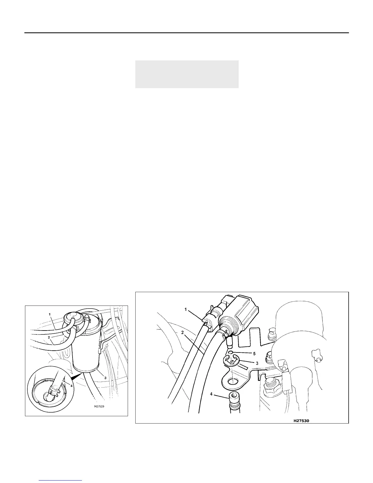
4 Release the clips and disconnect the hoses
from the top of the canister. Note their
locations for correct refitting, and pull the
hoses straight off the pipe stubs, otherwise
the stubs may break off inside the hose (see
illustration).
5 Where fitted, release the securing strap and
lift the canister from its location. On early
models, disconnect the additional hose at the
base of the canister.
6 Refitting is a reversal of removal, ensuring
that the hoses are correctly fitted.
Purge control valve solenoid (early
4-cylinder engines) - renewal
7 Disconnect the wiring multiplug from the
solenoid (see illustration).
8 Release the clip and disconnect the
vacuum hose from the solenoid. Pull the hose
straight off the pipe stub otherwise the stub
may break off inside the hose.
9 Extract the circlip from the purge hose at
the base of the solenoid and pull off the hose.
Recover the O-ring from the pipe stub,
ensuring that it doesn’t remain in the hose.
10 Slide the solenoid from its bracket and
remove it from the car.
11 Refitting is a reversal of removal, but use a
new O-ring on the purge hose stub.
Purge control valve solenoid (later
4-cylinder engines) - renewal
12 Disconnect the wiring multiplug from the
solenoid.
13 Release the clip and disconnect the
vacuum hose from the solenoid. Pull the hose
straight off the pipe stub otherwise the stub
may break off inside the hose.
14 Compress the retaining tags and
withdraw the solenoid from the charcoal
canister. Recover the O-ring from the base of
the solenoid.
15 Refitting is a reversal of removal, but use a
new sealing O-ring.
Thermostatic valve (V6 engines) -
renewal
16 Drain the cooling system as described in
Chapter 1.
17 Refer to Part D, Section 12, and remove
the fast idle valve.
18 Disconnect the two vacuum hoses at the
4E•2 Fuel and exhaust systems - Emissions control systems
2.7 Purge control valve solenoid attachments on early 4-cylinder engines
1 Wiring multiplug
2 Vacuum hose
3 Purge hose circlip
4 Purge hose
5 O-ring
2.4 Charcoal canister attachments on
V6 engines
1 Vacuum hose 3 Canister
2 Vapour hoses 4 Air inlet hose
1380 Rover 800 Series Remake


 To Next Page
 Loading...
