thermostatic valve and release the upper hose
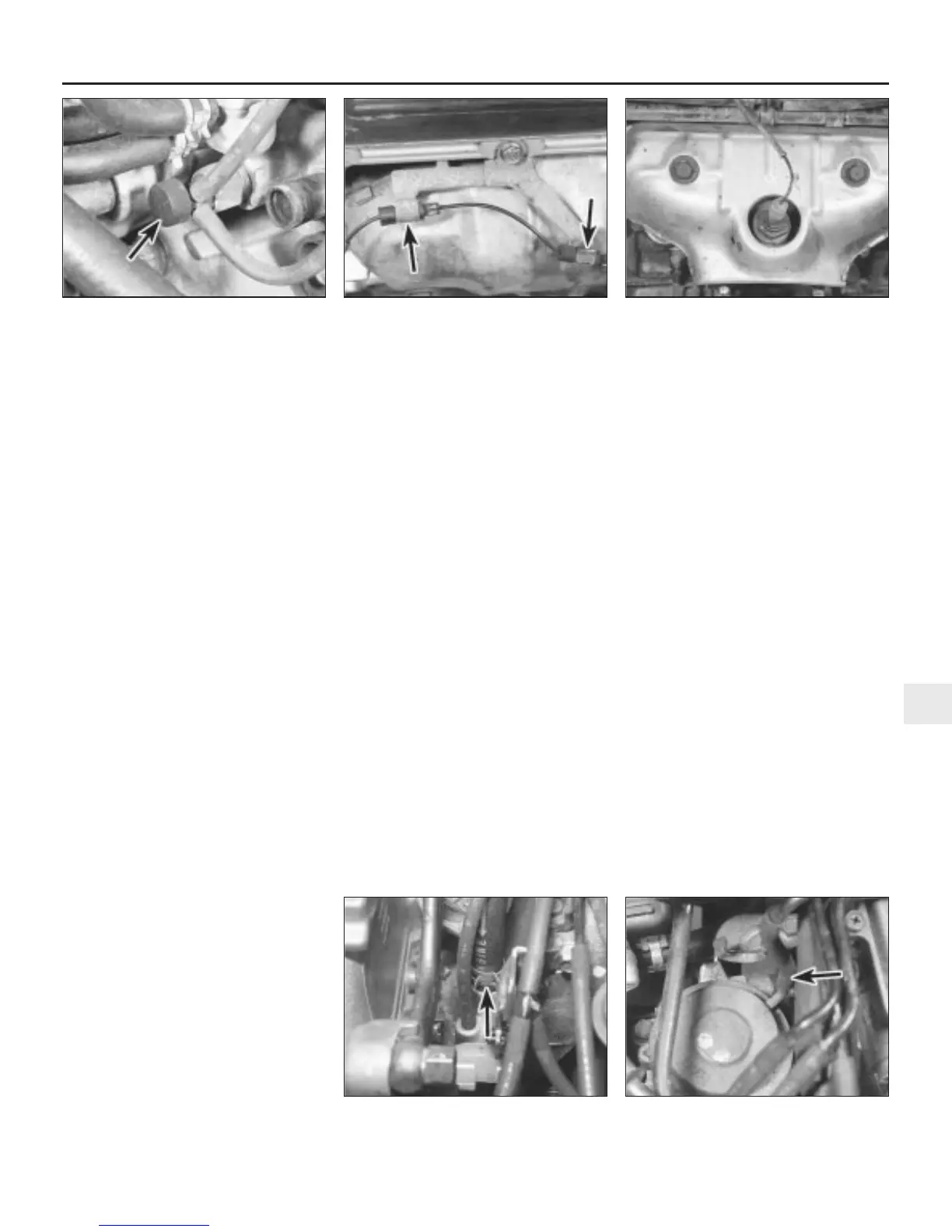
from its support clip (see illustration).
19 Unscrew the thermostatic valve from the
coolant passage and remove it from the
engine.
20 Refitting is a reversal of removal, but
apply a thread sealant to the valve threads
prior to refitting.
Constant vacuum control valve
(V6 engines) - renewal
21 The constant vacuum control valve is
located in the control box mounted on the
engine compartment bulkhead. Further
information on the control box and its
components can be found in Part D, Section 12.
Exhaust emissions control
Testing
22 Many of the exhaust emissions control
components are an integral part of the engine
management system, and testing can only be
accurately carried out using Rover test
equipment. On V6 engines, any system faults
will be stored in the ECU self-diagnosis
memory and displayed as a series of flashing
fault codes on the LED display. These can be
quickly interpreted by a dealer to isolate the
location of the fault and save time-consuming
individual component testing.
23 If a component is known to be faulty, or if
fault diagnosis has been carried out by a
dealer, it can then be renewed as follows.
Oxygen sensor (4-cylinder engines) -
renewal
Note: The oxygen sensor is delicate, and will
not work if it is dropped or knocked, if its
power supply is disrupted, or if any cleaning
materials are used on it.
24 On models with Lucas multi-point fuel
injection, the sensor is located on top of the
exhaust downpipe, under the car.
25 Disconnect the sensor wiring harness
multiplug at the connector in the engine
compartment. Release the harness from the
engine compartment cable ties and note the
harness routing.
26 Jack up the front of the car and securely
support it on axle stands.
27 Release the wiring harness from the
underbody cable ties.
28 Unscrew the sensor from the exhaust pipe
and collect the sealing washer.
29 Refitting is a reversal of removal using a
new sealing washer. Prior to installing the
sensor, apply a smear of high temperature
grease to the sensor threads. Ensure that the
sensor is securely tightened and make sure
that the wiring is routed correctly with no
danger of it contacting either the exhaust
system or engine.
30 On models with MEMS multi-point fuel
injection, the sensor is located in the exhaust
manifold.
31 Release the wiring harness from its
support bracket on the thermostat housing
and disconnect the harness multiplug.
32 Unscrew the sensor from the exhaust
manifold and collect the sealing washer.
33 Refitting is a reversal of removal using a
new sealing washer. Prior to installing the
sensor, apply a smear of high temperature
grease to the sensor threads and ensure that
the sensor is securely tightened.
Front oxygen sensor (V6 engines) -
renewal
34 Refer to the note at the beginning of
paragraph 24 before proceeding.
35 Refer to Chapter 3, and remove the
radiator.
36 Undo the three bolts securing the heat
shield to the exhaust manifold.
37 Disconnect the sensor lead at the wiring
connector and release the lead from the
support bracket clips (see illustration).
38 Remove the heat shield and unscrew the
sensor from the manifold.
39 Refitting is a reversal of removal using a
new sealing washer. Prior to installing the
sensor, apply a smear of high temperature
grease to the sensor threads and ensure that
the sensor is securely tightened. Refit the
radiator as described in Chapter 3.
Rear oxygen sensor (V6 engines) -
renewal
40 Refer to the note at the beginning of
paragraph 24 before proceeding.
41 Jack up the front of the car and securely
support it on axle stands.
42 From under the car, disconnect the
sensor lead at the wiring connector and
unscrew the sensor from the manifold (see
illustration).
43 Refitting is a reversal of removal using a
new sealing washer. Prior to installing the
sensor, apply a smear of high temperature
grease to the sensor threads and ensure that
the sensor is securely tightened.
Air suction valve (V6 engines) -
renewal
44 Disconnect the battery negative (earth)
lead (refer to Chapter 5, Section 1).
45 Release the clip and disconnect the brake
servo vacuum hose from the inlet manifold
(see illustration).
46 Undo the bolt securing the pipe bracket at
the rear of the air suction valve.
47 Disconnect the air suction valve vacuum
hose (see illustration).
Fuel and exhaust systems - Emissions control systems 4E•3
2.42 Rear oxygen sensor location in the
exhaust manifold
2.37 Release the oxygen sensor lead from
the support bracket clips (arrowed)
2.47 Disconnect the air suction valve
vacuum hose (arrowed)
2.45 Disconnect the brake servo vacuum
hose (arrowed) from the inlet manifold
4E
1380 Rover 800 Series Remake
2.18 Disconnect the two vacuum hoses at
the thermostatic valve (arrowed)


 To Next Page
 Loading...
