connected by its own wires to a spare battery;
the vehicle’s own battery is then
disconnected from the electrical system,
leaving the “memory-saver” to pass sufficient
current to maintain audio unit security codes
and ECU memory values, and also to run
permanently-live circuits such as the clock, all
the while isolating the battery in the event of a
short-circuit occurring while work is carried
out. Before using any of these devices, seek
the advice of a Rover dealer as to their
suitability for use on your car.
Warning: Some of these devices
allow a considerable amount of
current to pass, which can mean
that many of the vehicle’s
systems are still operational when the
main battery is disconnected. If a
“memory-saver” is used, ensure that the
circuit concerned is actually “dead” before
carrying out any work on it!
2 Battery -
removal and refitting
1
Note: Refer to the previous Section before
proceeding and also the relevant Sections of
Chapter 1.
Removal
1 The “sealed for life” battery is located on
the left-hand side of the engine compartment.
2 Slacken the negative (-) terminal clamp bolt
and lift the terminal off the battery post.
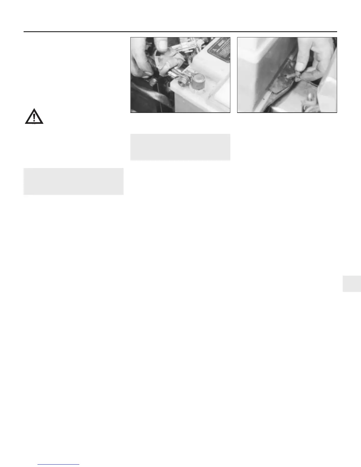
3 Lift the plastic cover from the positive (+)
terminal, slacken the clamp bolt and lift the
terminal off the battery post (see illustration).
4 Undo the retaining bolt and remove the
battery clamp plate (see illustration).
5 Lift the battery from the tray keeping it
upright and taking care not to touch any
clothing. Be careful - it’s heavy.
6 If required, the battery tray can be removed
after undoing the three retaining bolts.
7 Clean the battery terminal posts, clamps
and the battery casing. If the battery tray is
rusted as a result of battery acid spilling onto
it, clean it thoroughly and re-paint with
reference to Chapter 1.
8 If you are renewing the battery, make sure
that you get one that’s identical, with the
same dimensions, amperage rating, cold
cranking rating, etc. Dispose of the old battery
in a responsible fashion. Most local authorities
have facilities for the collection and disposal
of such items - batteries contain sulphuric
acid and lead, and should not be simply
thrown out with the household rubbish!
Refitting
9 Refitting is a reversal of removal. Smear the
battery terminals with a petroleum-based jelly
prior to reconnecting. Always connect the
positive terminal clamp first and the negative
terminal clamp last.
3 Ignition system - general
information and precautions
General information
4-cylinder engines
All 4-cylinder engine models covered by
this manual are equipped with a programmed
electronic ignition system, which utilizes
computer technology and electro-magnetic
circuitry to simulate the main functions of a
conventional ignition distributor.
A reluctor ring on the periphery of the
engine flywheel, and a crankshaft sensor
whose inductive head runs between the
reluctor ring teeth, replace the operation of
the contact breaker points in a conventional
system. The reluctor ring utilizes 34 teeth
spaced at 10º intervals, with two spaces, 180º
apart, corresponding to TDC for Nos 1 and 4
pistons, and Nos 2 and 3 pistons respectively.
As the crankshaft rotates, the reluctor ring
teeth pass over the crankshaft sensor, which
transmits a pulse to the ignition or ignition/fuel
electronic control unit (ECU) every time a
tooth passes over it. The ECU recognises the
absence of a pulse every 180º, and
consequently establishes the TDC position.
Each subsequent pulse then represents 10º of
crankshaft rotation. This, and the time interval
between pulses, allows the ECU to accurately
determine crankshaft position and speed.
A small bore pipe connecting the inlet
manifold to a pressure transducer within the
ECU supplies the unit with information on
engine load. From this constantly-changing
data, the ECU selects a particular advance
from a range of ignition characteristics stored
in its memory. The basic setting can be further
advanced or retarded, according to
information sent to the ECU from the coolant
temperature sensor, knock sensor and on
certain models, from the throttle pedal switch.
With the firing point established, the ECU
triggers the ignition coil, which delivers HT
voltage to the spark plugs in the conventional
manner. The cycle is then repeated many
times a second for each cylinder in turn.
In addition to the above operations, many
of the ignition system components have a
second function in the control and operation
of the fuel injection system. Further details will
be found in the appropriate Part of Chapter 4.
V6 engines
On all V6 engines a breakerless electronic
ignition system is used which comprises the
distributor, an igniter unit and the ignition coil.
The distributor is mounted on the left-hand
end of the front cylinder head and is driven
directly by the front camshaft. The ignition
system forms part of the engine management
package controlled by the fuel system
electronic control unit (ECU).
The distributor contains a reluctor mounted
on the distributor shaft, and a stator and pick-
up coil mounted on the baseplate. On 2.5 litre
engines the ignitor unit is attached to the side
of the distributor body, whereas on 2.7 litre
engines it is mounted separately at the rear
left-hand side of the engine compartment.
When the ignition is switched on, but the
engine is stationary, the transistors in the
igniter unit prevent current flowing through the
ignition system primary (LT) circuit. As the
crankshaft rotates, the reluctor moves
through the magnetic field created by the
stator. When the reluctor teeth are in
alignment with the stator projections, a small
AC voltage is created and sensed by the pick-
up coil. The igniter uses this voltage to switch
the transistors in the unit and completes the
ignition system primary (LT) circuit.
As the reluctor teeth move out of alignment
with the stator projections, the AC voltage
changes and the transistors in the igniter are
switched again to interrupt the primary (LT)
circuit. This causes a high voltage to be
induced in the coil secondary (HT) windings
which then travels down the HT lead to the
distributor and onto the relevant spark plug.
On 2.5 litre engines ignition advance is
controlled by both centrifugal and vacuum
operated systems. Centrifugal advance is
controlled by engine speed whereas vacuum
advance is controlled by the ignition control
system. This system uses solenoid valves and
sensors to apply vacuum to one of the two
distributor vacuum diaphragms dependant on
engine operating parameters. Sensors
Engine electrical systems 5•3
2.4 Removing the battery clamp retaining
bolt
2.3 Lift off the plastic cover for access to
the battery positive terminal
5
1380 Rover 800 Series Remake


 To Next Page
 Loading...
