monitor manifold pressure, coolant
temperature, intake air temperature,
atmospheric pressure and engine speed and
pass signals to the fuel system ECU.
According to the signals received, the ECU
controls the operation of the solenoid valves
to provide the appropriate vacuum necessary
to create the required ignition advance.
On 2.7 litre engines ignition advance is
controlled entirely by the fuel system ECU. As
with the 2.5 litre engines, sensors monitor
engine parameters and send signals to the
ECU accordingly. From the information
received, the required ignition advance is
determined by the ECU for all engine operating
conditions. In addition to the sensors
described for 2.5 litre engines, 2.7 litre models
also utilise a crank/cylinder sensor, mounted
just behind the front camshaft sprocket, to
detect the TDC position for No 1 cylinder and
to determine engine speed and piston position.
An additional TDC sensor, mounted in the
distributor, is used to provide a fixed ignition
timing setting during engine cranking and as a
back-up unit should the crank/cylinder sensor
fail, or produce erroneous signals.
In addition to the above operations, many
of the ignition system components have a
second function in the control and operation
of the fuel injection system. Further details will
be found in the appropriate Part of Chapter 4.
Precautions
When working on the ignition system, take
the following precautions:
(a) Do not keep the ignition switched on for
more than 10 seconds if the engine will
not start.
(b) If a separate tachometer is ever required
for servicing work, consult a dealer
service department before buying a
tachometer for use with this vehicle -
some tachometers may be incompatible
with these types of ignition systems - and
always connect it in accordance with the
equipment manufacturer’s instructions.
(c) Never connect the ignition coil terminals
to earth. This could result in damage to
the coil and/or the ECU or igniter unit.
(d) Do not disconnect the battery when the
engine is running.
(e) Refer to the warning at the beginning of
the next Section concerning HT voltage.
4 Ignition system - testing
2
Warning: Voltages produced by
an electronic ignition system are
considerably higher than those
produced by conventional ignition
systems. Extreme care must be taken when
working on the system if the ignition is
switched on. Persons with surgically-
implanted cardiac pacemaker devices
should keep well clear of the ignition circuits,
components and test equipment.
General
1 The components of the electronic ignition
system are normally very reliable; most faults
are far more likely to be due to loose or dirty
connections, or to “tracking” of HT voltage
due to dirt, dampness or damaged insulation,
than to the failure of any of the system’s
components. Always check all wiring
thoroughly before condemning an electrical
component, and work methodically to
eliminate all other possibilities before deciding
that a particular component is faulty.
2 The old practice of checking for a spark by
holding the live end of an HT lead a short
distance away from the engine is not
recommended; not only is there a high risk of
a powerful electric shock, but the HT coil,
ECU or igniter unit may be damaged.
Similarly, never try to “diagnose” misfires by
pulling off one HT lead at a time.
Engine will not start
3 If the engine either will not turn over at all,
or only turns very slowly, check the battery
and starter motor. Connect a voltmeter across
the battery terminals (meter positive probe to
battery positive terminal) then note the voltage
reading obtained while turning the engine over
on the starter for (no more than) ten seconds.
If the reading obtained is less than
approximately 9.5 volts, first check the
battery, starter motor and charging system as
described in the relevant Sections of this
Chapter.
4 If the engine turns over at normal speed but
will not start, check the HT circuit by
connecting a timing light (following its
manufacturer’s instructions) and turning the
engine over on the starter motor; if the light
flashes, voltage is reaching the spark plugs,
so these should be checked first. If the light
does not flash, check the HT leads
themselves, followed by the distributor cap,
carbon brush and rotor arm, using the
information given in Chapter 1.
5 If there is a spark, check the fuel system for
faults, referring to the relevant part of Chap-
ter 4 for further information.
6 If there is still no spark, check the condition
of fuse 15 (early models) or fuse 19 (later
models) in the passenger compartment
fusebox. If the fuse is sound, check the
voltage at the ignition coil “+” terminal (light
green wire on V6 engines and early 4-cylinder
engines, brown/pink wire on later 4-cylinder
engines); it should be the same as the battery
voltage (ie, at least 11.7 volts). If the voltage at
the coil is more than 1 volt less than that at
the battery, check the condition of all the
circuit wiring, referring to the wiring diagrams
at the end of this manual.
7 If the feed to the coil is sound, check the
coil’s primary and secondary winding
resistance as described later in Section 7. If
faulty, a new coil should be fitted. However,
check carefully the condition of the LT
connections themselves before doing so, to
ensure that the fault is not due to dirty or
poorly-fastened connectors.
8 If the coil is in good condition, the fault is
probably within the crankshaft sensor or the
fuel or ignition ECU on 4-cylinder engines, or
within the pick-up coil, igniter, or fuel ECU on
V6 engines. Testing of these components
should be entrusted to a Rover dealer.
Engine misfires
9 An irregular misfire suggests either a loose
connection or intermittent fault on the primary
circuit, or an HT fault on the coil side of the
rotor arm.
10 With the ignition switched off, check
carefully through the system, ensuring that all
connections are clean and securely fastened.
If the equipment is available, check the LT
circuit as described above.
11 Check that the ignition coil, the distributor
cap and the HT leads are clean and dry.
Check the leads themselves and the spark
plugs (by substitution if necessary), then
check the distributor cap, carbon brush and
rotor arm as described in Chapter 1.
12 Regular misfiring is almost certainly due to
a fault in the distributor cap, HT leads or spark
plugs. Use a timing light (paragraph 4 above)
to check whether HT voltage is present at all
leads.
13 If HT voltage is not present on any
particular lead, the fault will be in that lead, or
in the distributor cap. If HT is present on all
leads, the fault will be in the spark plugs;
check and renew them if there is any doubt
about their condition.
14 If no HT is present, check the ignition coil;
its secondary windings may be breaking
down under load.
5 Distributor cap and rotor
arm - removal and refitting
1
Removal
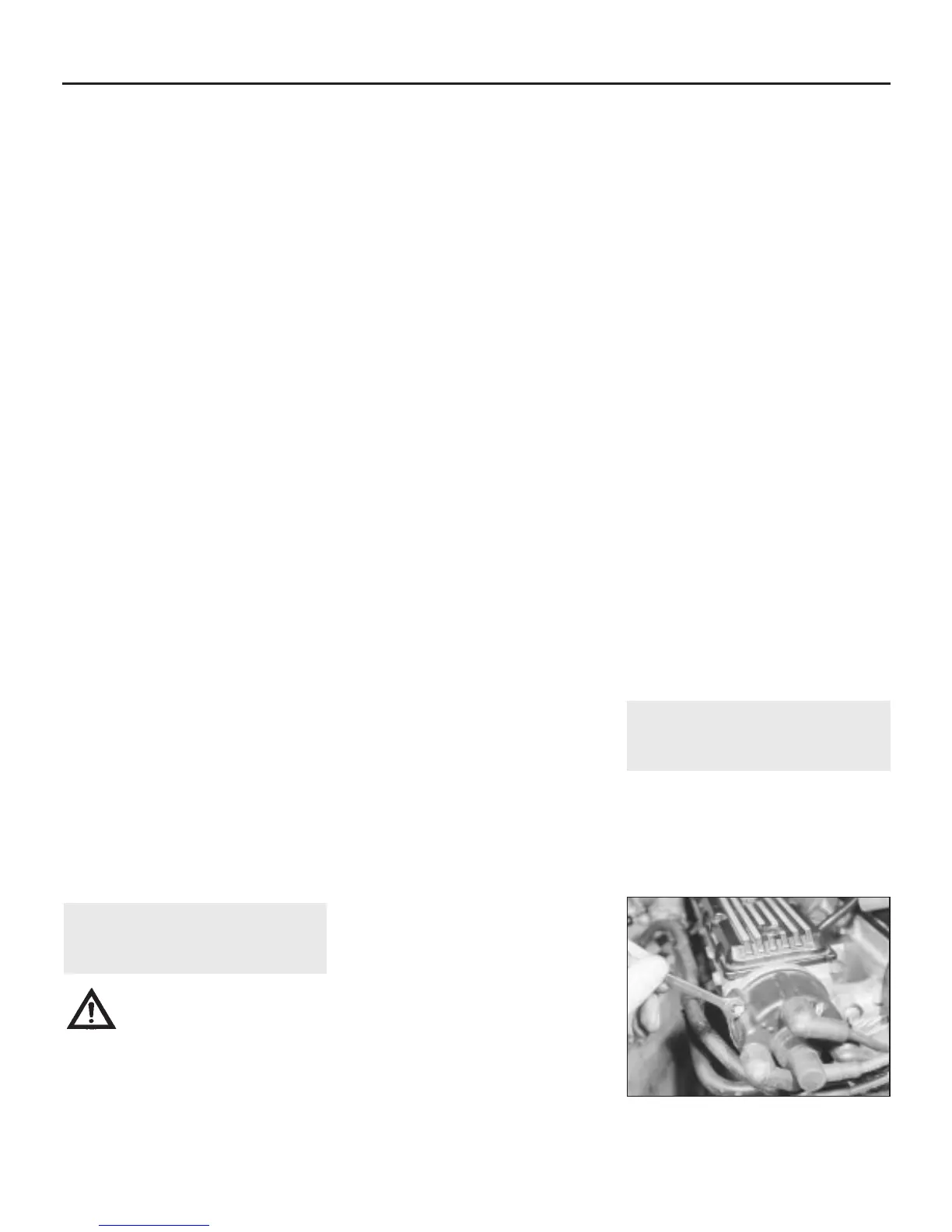
1 Using an open-ended spanner, undo the
two retaining screws and lift off the distributor
cap from the cylinder head or distributor as
applicable (see illustration). On V6 engines,
recover the large O-ring seal from the base of
5•4 Engine electrical systems
5.1 Undo the two retaining screws and lift
off the distributor cap
1380 Rover 800 Series Remake


 To Next Page
 Loading...
