marks. The centre notch of the three (usually
coloured red) represents 15º BTDC. The
remaining two notches represent a timing
tolerance of ± 2º (see illustration 10.4).
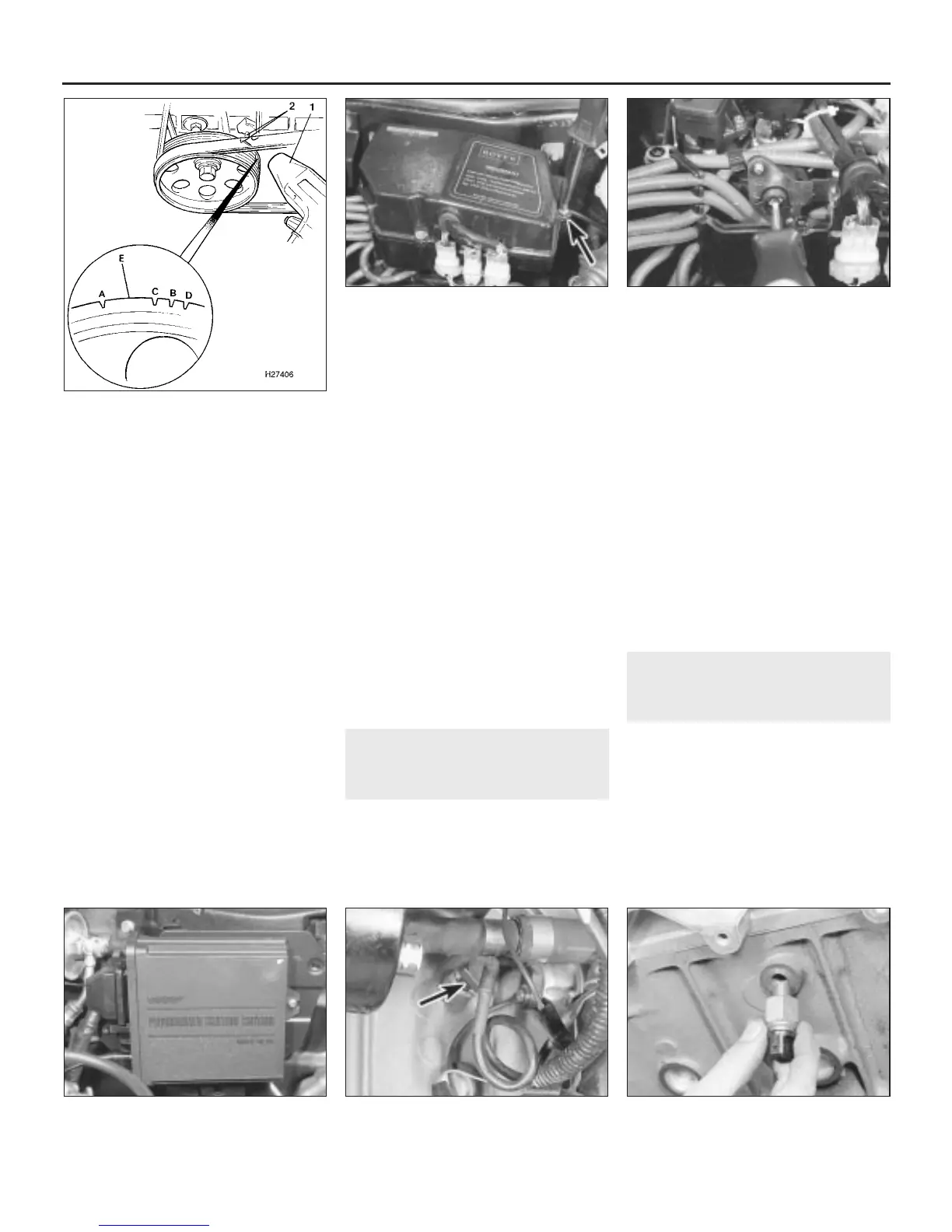
21 If the engine is being adjusted to run on
unleaded fuel, it will be necessary to make an
additional notch on the pulley (the existing
notches are only applicable when adjusting
for use with leaded fuel). To do this, measure
the distance from notch C to notch B and
make an additional notch E, that distance
from C (see illustration). Use a small file to
make the new notch.
22 Once the marks have been located, it is a
good idea to highlight them, and the pointer
on the timing belt cover, with a dab of quick-
drying white paint to make them easily
recognisable when using the timing light.
23 Start the engine and allow it to warm up to
normal operating temperature. Check that the
idling speed is correct and, if necessary,
adjust it as described in Chapter 1.
24 Switch the engine off and connect the
timing light to No 1 cylinder plug lead as
described in the timing light manufacturer’s
instructions. No 1 cylinder is on the rearmost
cylinder at the crankshaft pulley end (beneath
the brake master cylinder).
25 Start the engine again and allow it to idle.
Point the timing light at the timing marks. The
pointer on the timing belt cover should be
aligned with the appropriate notch on the
crankshaft pulley.
26 If adjustment is required, slacken the two
screws securing the control box to the engine
compartment bulkhead. Undo the three
screws and lift off the control box upper cover
(see illustration).
27 Engage a small screwdriver with the
adjustment slot in the ignition timing adjuster
and turn the adjuster clockwise to advance
the timing or anti-clockwise to retard it (see
illustration).
28 Make a final check of the setting, then
switch off the engine and disconnect the
timing light. Refit the control box cover and
the access cover under the wheelarch.
11 Electronic control unit -
removal and refitting
1
Note: The following procedure is applicable to
4-cylinder engines with multi-point fuel
injection which use a separate ECU for the
ignition system. For all other engines the
ignition system is controlled by the fuel system
ECU and reference should be made to the
procedures contained in the relevant Parts of
Chapter 4.
Removal
1 Disconnect the battery negative (earth) lead
(refer to Section 1 before doing this).
2 Disconnect the wiring multiplug from the
ECU (located on the left-hand side of the
engine compartment), either behind the
battery or on the bulkhead (see illustration).
To do this, press the retaining tab upwards,
release the bottom of the multiplug, then
disengage the top lug.
3 Disconnect the vacuum supply hose.
4 Undo the retaining screw, slide the unit out
of its mounting bracket to disengage the
retaining lug, and remove the ECU.
Refitting
5 Refitting is a reversal of removal.
12 Knock sensor -
removal and refitting
1
Removal
1 The knock sensor (4-cylinder engines only)
is located in the centre of the rear-facing side
of the cylinder block, beneath the inlet
manifold.
2 Jack up the front of the car and support it
on stands.
3 Disconnect the wiring multiplug, then
unscrew the sensor from its location (see
illustrations).
5•8 Engine electrical systems
12.3a Disconnect the knock sensor
multiplug (arrowed) . . .
11.2 Ignition ECU location on the engine
compartment bulkhead
10.27 Turn the ignition timing adjuster to
advance or retard the timing
10.26 Undo the three screws and lift off
the control box upper cover
1380 Rover 800 Series Remake
10.21 Ignition timing adjustment on
2.7 litre engines
1 Timing light
2 Timing cover pointer and TDC notch
A Pulley TDC notch
B 15º BTDC notch
C 13º BTDC notch
D 17º BTDC notch
E New notch position (11º BTDC) for
unleaded fuel setting
12.3b . . . then unscrew the sensor


 To Next Page
 Loading...
