Refitting
4 Refitting is a reversal of removal, but ensure
that the sensor and cylinder block mating
faces are clean.
13 Crankshaft sensor -
removal and refitting
1
Removal
1 The crankshaft sensor, fitted to 4-cylinder
engines is attached to the transmission
adaptor plate on the rear facing side of the
engine.
2 Jack up the front of the car and support it
on stands.
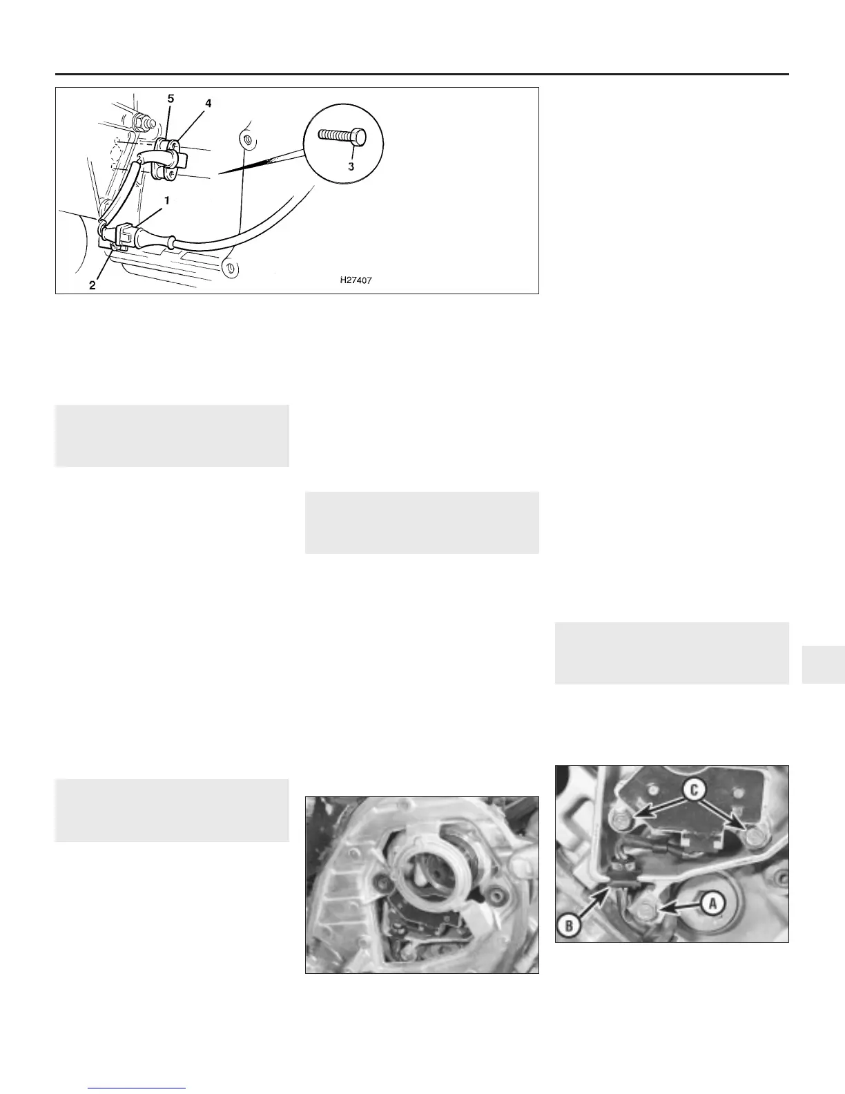
3 Disconnect the multiplug from the
crankshaft sensor wiring socket (see
illustration).
4 Undo the retaining screw and remove the
wiring socket from its mounting bracket.
5 Undo the two bolts securing the crankshaft
sensor to the adaptor plate, and withdraw the
sensor, complete with spacer and wiring
socket.
Refitting
6 Refitting is a reversal of removal, but ensure
that the sensor and cylinder block mating
faces are clean.
14 Crank/cylinder sensor -
removal and refitting
4
Removal
1 The crank/cylinder sensor is located behind
the timing belt sprocket on the front facing
cylinder head of V6 engines.
2 Remove the timing belt and the front
camshaft sprocket as described in Chapter 2,
Part B.
3 Undo the four bolts and remove the timing
belt backplate from the front cylinder head
(see illustration).
4 Disconnect the crank/cylinder sensor wiring
multiplug and undo the cable clip retaining
bolt. Slip the sensor wiring harness grommet
out of the slot in the cylinder head (see
illustration).
5 Undo the two bolts and withdraw the
sensor from its location.
Refitting
6 Refitting is a reversal of removal. Refer to
Chapter 2, Part B for timing belt refitting and
adjustment procedures.
15 Charging system - general
information and precautions
General information
The charging system includes the
alternator, an internal voltage regulator, a no-
charge (or “ignition”) warning light, the
battery, and the wiring between all the
components. The charging system supplies
electrical power for the ignition system, the
lights, and all the cars accessories. The
alternator is driven by the alternator (auxiliary)
drivebelt from the crankshaft pulley.
The purpose of the voltage regulator is to
limit the alternator’s voltage to a preset value.
This prevents power surges, circuit overloads,
etc., during peak voltage output.
The charging system doesn’t ordinarily
require periodic maintenance. However, the
drivebelt, battery and the wires and
connections should be inspected at the
intervals outlined in Chapter 1.
The instrument panel warning light should
come on when the ignition key is turned to
positions “II” or “III”, then should go off
immediately the engine starts. If it remains on, or
if it comes on while the engine is running, there
is a malfunction in the charging system (see
Section 16). If the light does not come on when
the ignition key is turned, and the bulb is sound
(see Chapter 12), there is a fault in the alternator.
Precautions
Be very careful when making electrical
circuit connections to a vehicle equipped with
an alternator, and note the following:
(a) When reconnecting wires to the alternator
from the battery, be sure to note the polarity.
(b) Before using arc-welding equipment to
repair any part of the vehicle, disconnect
the wires from the alternator and the
battery terminals.
(c) Never start the engine with a battery
charger connected.
(d) Always disconnect both battery leads
before using a battery charger.
(e) The alternator is driven by an drivebelt
which could cause serious injury if your
hand, hair or clothes become entangled in
it with the engine running.
(f) Because the alternator is connected
directly to the battery, it could arc or
cause a fire if overloaded or shorted-out.
(g) Wrap a plastic bag over the alternator, and
secure it with rubber bands, before steam-
cleaning or pressure-washing the engine.
(h) Never disconnect the alternator terminals
while the engine is running.
16 Charging system - testing
2
1 If a malfunction occurs in the charging
circuit, don’t automatically assume that the
alternator is causing the problem. First check
the following items:
Engine electrical systems 5•9
13.3 Crankshaft sensor attachments
14.4 Crank/cylinder sensor attachments
A Cable clip retaining bolt
B Wiring harness grommet
C Sensor retaining bolts
14.3 Remove the timing belt backplate
from the front cylinder head
5
1380 Rover 800 Series Remake
1 Wiring multiplug
2 Wiring socket
retaining screw
3 Sensor retaining
bolts
4 Crankshaft sensor
5 Spacer


 To Next Page
 Loading...
