with compressed air and do not inhale any
of it. DO NOT use petroleum-based
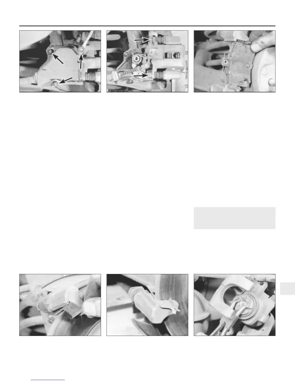
solvents to clean brake parts. Use brake
cleaner or methylated spirit only. DO NOT
allow any brake fluid, oil or grease to
contact the brake pads or disc. Also refer
to the warning at the start of Section 2
concerning the dangers of hydraulic fluid.
Note: New caliper guide pin bolts will be
required for refitting.
1 Chock the front wheels, remove the wheel
trim and slacken the rear wheel nuts. Jack up
the rear of the car and support it on axle
stands. Remove the rear roadwheels and
ensure that the handbrake is released.
2 On early models, undo the three handbrake
linkage cover securing bolts and remove the
cover from the caliper (see illustrations).
3 Where fitted, disconnect the pad wear
warning light wiring plug (left-hand caliper).
4 Using a spanner, unscrew the upper and
lower guide pin bolts (see illustration).
5 Withdraw the caliper and handbrake linkage
assembly from the brake pads and carrier
bracket.
6 Lift out the two brake pads, then, where
fitted, remove the upper and lower anti-rattle
shims from the caliper carrier bracket (see
illustrations). If the pads are to be re-used,
identify them so that they can be refitted in
their original positions.
7 Brush the dust and dirt from the caliper,
piston, disc, and pads, but do not inhale it, as
it is injurious to health.
8 Rotate the disc by hand, and scrape away
any rust and scale. Carefully inspect the entire
surface of the disc, and if there are any signs
of cracks, deep scoring or severe abrasions,
the disc must be renewed.
9 Inspect the caliper for fluid leaks around the
piston, signs of corrosion, or other damage.
Check the guide pin rubber boots for
condition, and the pins themselves for free
movement in the carrier bracket. Renew any
suspect parts as necessary, with reference to
Section 9.
10 If new pads are to be fitted, it will be
necessary to screw the caliper piston into its
bore to accommodate the new, thicker pads.
Remove the dust cap and fit a tube over the
end of the bleed screw. Submerge the free
end of the tube in a jar containing a small
quantity of brake fluid.
11 Open the bleed screw approximately half
a turn, then screw the piston back fully into its
bore by turning it clockwise with a pair of
angled circlip pliers or other similar tool (see
illustration). If necessary, turn the piston up
to 1/4 turn anti-clockwise so that one of
the cutouts will align with the projection on
the inboard pad. Now close the bleed
screw, remove the tube and refit the
protective cap.
12 To refit the pads, first place the anti-rattle
shims (where fitted) in position in the carrier
bracket.
13 Fit the pads to the carrier bracket, noting
that the pad with the warning light lead (left-
hand caliper only) must be fitted nearest to
the centre of the car.
14 Place the caliper over the pads, and
secure with new guide pin bolts, tightened to
the specified torque.
15 Refit the warning light wiring plug (where
applicable) and the handbrake linkage cover.
16 Depress the brake pedal several times to
automatically adjust the brake pads and the
handbrake linkage. Do not apply the
handbrake until the rear pads have self-
adjusted otherwise incorrect brake operation
will result.
17 Repeat the above procedure on the
opposite rear brake unit.
18 Check, and if necessary top up, the fluid
in the master cylinder reservoir then refit the
roadwheels and lower the car to the ground.
Tighten the roadwheel nuts to the specified
torque and refit the wheel trim.
8 Rear brake caliper -
removal and refitting
3
Note: Before starting work, refer to the
warning at the beginning of Section 2
concerning the dangers of hydraulic fluid, and
to the warning at the beginning of Section 7
concerning the dangers of asbestos dust.
Note: New caliper guide pin bolts and brake
hose copper washers will be required for
refitting.
Braking system 9•7
7.6a Lift out the two brake pads . . .7.4 Rear caliper upper and lower guide pin
bolt locations (arrowed)
7.2b Undo the three handbrake linkage
cover retaining bolts (arrowed)
7.11 Using angled circlip pliers to screw
the piston back into the caliper. Note the
position of the cut-outs
7.6c . . . and lower anti-rattle shim7.6b . . . followed by the upper anti-rattle
shim . . .
9
1380 Rover 800 Series Remake


 To Next Page
 Loading...
